
Page 24 - Shroeder - Filter Systems
P. 24
Analyzing the Data
Example of a 5. Analysis method
Cleanliness The flushing method should be used for component analysis. The surfaces of the component are flushed
in a clean environment using x ml of the test fluid (XY) which has a cleanliness of xx, under a pressure of
Specification z psi as specified by the inspection and testing plan. The flushed-off particulate contamination is
continued collected on an analysis membrane and subjected to gravimetric analysis. Representative samples are
taken of the system fluids at the specified sampling points. All testing parameters are specified; the
duration of testing, what is tested, the pressures, and speeds. When conducting static inspection and
testing make sure that a flushing effect is present so that the cleanliness of these components can be
determined, (the static pressure test has to be followed by a dynamic flushing process in order to analyze
the actual quantity of particles which is flushed out of the component.)
6. Evaluation method
In the component analyses the analysis membrane is dried until it achieves a constant weight, and then
cooled in a defined dry environment and weighed. This procedure is repeated subsequent to filtration.
The weight differential indicates the “gravimetric contamination” of the component. This is followed
by visually examining the analysis membranes through a microscope and measuring the longest particles.
Evaluation of the fluid samples is done in accordance with ISO 4405, ISO 4407, ISO 4406:1999 or
NAS 1638.
7. Accuracy
The analysis equipment has to be brought to a residual dirt content of 0.2 mg prior to conducting
the analysis so that the measurements taken of the component samples are sufficiently accurate. This is
determined by performing a negative control, i.e. flushing the equipment without testing. When the
result of the analysis drops below 0.5 mg, the batch size is to be increased and thus a mean value of the
results computed.
8. Analysis fluids to be used
The following analysis fluid should be used for the component analyses: ABC-XX, with a cleanliness class
of 14 / 12 / 9 and no particles > 40 µm.
9. Documentation
The documentation of the results is done using a result sheet.
10. Limit values
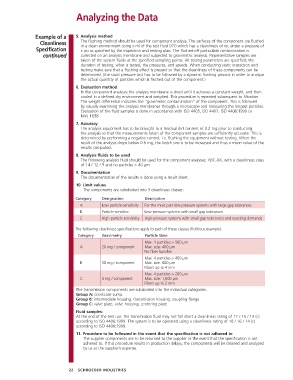
The components are subdivided into 3 cleanliness classes:
Category Designation Description
A Low particle-sensitivity For the most part low-pressure systems with large gap tolerances
B Particle-sensitive Low-pressure systems with small gap tolerances
C High particle sensitivity High-pressure systems with small gap tolerances and exacting demands
The following cleanliness specifications apply to each of these classes (fictitious example).
Category Gravimetry Particle Sizes
Max. 4 particles > 500 µm
A 20 mg / component Max. size: 400 µm
No fiber bundles
Max. 4 particles > 400 µm
B 10 mg / component Max. size: 800 µm
Fibers up to 4 mm
Max. 4 particles > 200 µm
C 5 mg / component Max. size: 1,000 µm
Fibers up to 2 mm
The transmission components are subdivided into the individual categories.
Group A: crankcase sump.
Group B: intermediate housing, transmission housing, coupling flange
Group C: valve plate, valve housing, centering plate
Fluid samples:
At the end of the test run, the transmission fluid may not fall short a cleanliness rating of 17 / 15 / 13 (c)
according to ISO 4406:1999. The system is to be operated using a cleanliness rating of 18 / 16 / 14 (c)
according to ISO 4406:1999.
11. Procedure to be followed in the event that the specification is not adhered to
The supplier components are to be returned to the supplier in the event that the specification is not
adhered to. If this procedure results in production delays, the components will be cleaned and analyzed
by us at the supplier’s expense.
22 SCHROEDER INDUSTRIES