
Page 23 - Shroeder - Filter Systems
P. 23
Analyzing the Data
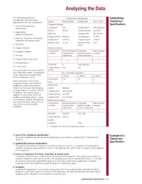
The following parameters Contamination Management Establishing
are defined in the cleanliness Cleanliness
specifications for the components: System Power Steering Analysis date Jan. 31, 2001
Component analysis Specifications
1. Goal of the cleanliness
specification Component Rack Sampling point After washing 1
Part No. Xx1235 Sample taken by Joe Smith
2. Applicability
(system designation) Batch size 1 Sampling date Jan. 30, 2001
Analysis method Ultrasonic Lot designation 01-2001
3. Extent of inspection and testing;
inspection and testing cycles Analysis fluid COLD-02 Analysis fluid vol. 1,500 ml
Negative value .02 mg Membrane filter 7 µm
4. Sampling rating
5. Analysis method Evaluation method
6. Evaluation method In-line particle Automated particle Automated Manual particle
counting counting of the particle counting counting
7. Accuracy analysis fluid of the membrane
8. Analysis fluids to be used x
x
9. Documentation
Gravimetry 8 mg/component
10. Limit values
Largest abrasive 350 µm
This specification has to be made for particle
each individual system; consequently No. of particles / component
a few things are discussed which > 50 µm > 100 µm > 200 µm
have to be borne in mind.
Actual value 100 10 3
Work instructions concerning Limit 0
sampling, analysis and evaluation
methods should be described in System Fluid
detail so as to ensure that sampling System Washing 1
is always done in a uniform manner. Sampling point Flushing bath
In addition, the analysis results
depend on the analysis fluid and Sample taken by Joe Smith
method, particularly when it comes Sampling date Jan. 30, 2001
to component analysis. Docu menta- Measurement method
tion should be done using forms so In-line particle Automated particle Automated Manual particle
that all the results are readily counting counting of the particle counting counting
accessible.
analysis fluid of the membrane
x
ISO 4406 22/20/18 NAS 1638
Largest abrasive 300 µm
particle
Signature: Date:
Example of a form for entering findings
1. Goal of the cleanliness specification Example of a
The goal in implementing this cleanliness specification is to achieve a constant level of cleanliness for Cleanliness
system X.
Specification
2. Applicability (system designation)
This specification applies to system X including its series A, B, and C. It extends to all components
whether sourced or manufactured in house. It also specifies the system fluids of system X with regard to
their cleanliness.
3. Extent of inspection & testing; inspection & testing cycles
5 samples a month of each component are to be taken and analyzed. If the supplier parts achieve a
constant cleanliness value after 6 months, the sampling cycle can be extended to every 2 or 3 months.
An analysis of the entire (assembled) system is to be done at least once a week prior to delivery.
Checking of the fluid cleanliness should be done on a continuous basis.
4. Sampling
Sampling of components is to be done at receiving and is to be representative. Samples should be
packed in a dust-tight manner and sent into the laboratory. The fluid samples are to be taken at the
sampling points indicated in the inspection and testing plan.
SCHROEDER INDUSTRIES 21