


Page 14 - Destaco - SpiderGrip Geometric End Effector System
P. 14
SpiderGrip End Effector Tooling Systems


                                                          Spidergrip Tooling Components | Assembly Instructions


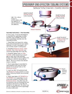
                                         Model Number#
                                         STCCLR2-NA/90                                          Model Number#
                                         Collar Assembly                                        STCXKEY-NA/90
                    M8-1.25 x 40mm                                                              X-Key Assembly
                    Torque to
                    25 N*m [220 in-lb]
                    (for Ø60mm) or
                    30 N*m [265 in-lb]
                    (for Ø90mm)


                                                     PATENT PENDING


            Assembly Instructions – First Assembly
            In many cases, it may be advantageous
            to assemble the appendage remotely
            and then once complete, mount the                                                     Model Number#
            entire appendage assembly onto the                                                    STS0016-NA(shown)
            mounting structure.                                                                   or STS0017-90
                                                                                                  Anchor Mount
            1. Clean/Wipe and inspect ALL mating
            faces of all components for burrs before
            assembly; if a part is damaged it will
            not correctly couple to mating piece.
            2. Assemble Breakaway Anchor, X-Key
            Assembly, New Collar Assembly and
            remaining appendage (from step #3).

            3. Gradually tighten bolts on Collar
            Assembly, while maintaining an equal
            gap on each side of the assembly.
            Torque collar bolts to 25 N*m [220 in-lb]
            for 60mm, or 30 N*m 265 [in-lb] for
            90mm.  Do not re-torque once desired
            torque is reached.

            4. Mount appendage as assembled to
            steel backbone and insert new 8mm
            dowels into the dowel holes on the
            Breakaway Anchor.                                                                              Equal
            5. Insert new M8-1.25 patchlock bolts                                                          distance
            into Breakaway Anchor, torque in a cross                                                       between
            pattern following NAAMS recommended                                                            collars.
            torque.
            6. Attach steel tether (STS-TETHER-08 or
            STS-TETHER-16) to appendage via one
            of the bolts located on the base of the
            Breakaway Anchor. The other loop will
            be attached to the first threaded M6 hole
            (located on the boom) or the M8 hole
            located on the edge part. The tether may
            also be wrapped around the appendage
            to reduce cable slack.


            Dimensions and technical information are subject to change without notice  EE-SGP-14

