
Page 73 - Schroeder - Accessories
P. 73
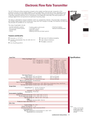
Electronic Flow Rate Transmitter


            The HFT 2100 series of flow transmitters is based on the variable area float principle. Irrespective of the   HFT-2100  Air Breathers
            installation position, the test medium deflects a spring-loaded float in the direction of flow, depending on the
            flow rate. A Hall sensor which detects the position of the float, is fitted to the outside of the instrument and   Suction
            is therefore separate to the flow circuit. In proportion to the deflection of the float, the sensor produces an
            analogue signal which corresponds to the particular measuring range.                                Separators
                                                                                                                     and
            The device is calibrated for vertical installation and for an upwards flow direction. The transmitter is designed to   Strainers
            give reliable measurements within its accuracy range, even with changes in viscosity. The kinematic viscosity may
            vary between 30 and 600 cSt (141-2727 SUS).
                                                                                                                  Oil Sight
            The areas of application include:                                                                      Glasses
            - Central lubrication systems   - Cooling systems and circuits   - Chemical industry
            - Oil circuit lubrication systems   - Lubrication circuits   - Research & development
            - Transformers             - Hydraulic systems                                                       Electronic
            - Pumps                    - Welding machines and laser systems                                       Sensors

                                                                                                                Fluid Level
            Features and Benefits                                                                                Indicators
                ■ Accuracy ≤ ± 10 % FS                   ■ High level of functional reliability
                ■ Viscosity compensation from 30..600 cSt (141-    ■ High pressure resistance
               2727 SUS)                                 ■ Threaded connection
                ■ Any mounting position


              Input Data                                                                       Specifications
                               Measuring Ranges: Size 1:            Size 2:
                                             0.13 - 0.42 gpm (0.5 - 1.6 L/min)  0.13 - 0.39 gpm (0.5 - 1.5 L/min)
                                             0.21 - 0.79 gpm (0.8 - 3.0 L/min)  0.26 - 1.05 gpm (1 - 4 L/min)
                                             0.53 - 1.85 gpm (2.0 - 7.0 L/min)  0.53 - 2.11 gpm (2 - 8 L/min)
                                                                    0.79 - 2.64 gpm (3 - 10 L/min)
                                                                    1.32 - 3.96 gpm (5 - 15 L/min)
                                                                    2.11 - 6.34 gpm (8 - 24 L/min)
                                                                    2.64 - 7.92 gpm 10 - 30 L/min)
                                                                    3.96 - 11.88 gpm (15 - 45 L/min)
                                                                    5.28 - 15.85 gpm (20 - 60 L/min)
                                                                    7.92 - 23.77 gpm (30 - 90 L/min)
                                                                    9.24 - 29.05 gpm (35 - 110 L/min)
                               Operating Pressure:
                                    Brass Version 4351 psi (300 bar)   3625 psi (250 bar)
                             Stainless Steel Version 5076 psi (350 bar)  4351 psi (300 bar)
                                   Pressure Drop: 0.3 - 3 psi (0.02-0.2 bar)  5076 psi (350 bar)
                            Mechanical Connection: See dimensions
                       Parts in Contact with Medium:
                                    Brass Version Stainless Steel 1.4571; FPM 1 ; Brass, Nickel-plate; Brass; Hard Ferrite
                             Stainless Steel Version Stainless Steel 1.4571; FPM 1 ’ Hard Ferrite
             Output Data
                                  Output Signal: 4 .. 20 mA, 3 Conductor
                                             0 .. 10 V, 3 Conductor
                                     Accuracy 2 : ≤ ±  10% FS
                                   Repeatability: 1% FS max.
             Environmental Conditions
                       Operating Temperature Range: -4°F to 158°F (-20°C to 70 °C)
                           Fluid Temperature Range: -4°F to 158°F (-20°C to 70 °C)
                                  Viscosity Range: 30 .. 600 cSt  (141 - 2727 SUS)
                                          Mark: Directive 2004 / 108 / EC
                         Protection class to IEC 60529: IP 67
             Other Data
                                  Supply Voltage: 18 .. 30 V
                              Power Consumption: < 1 W                                         Notes:
                              Electrical Connection:  Male Connection M12x1                         1) Other seal materials
                                Housing Material:                                                   available upon request
                                  Measuring Body Brass (nickel-plated) or st. steel 1.4571          2) 3% possible with
                                                                                                    calibration to a certain
                                     Transmitter Brass (nickel-plated)                              viscosity
                                                                       SCHROEDER INDUSTRIES   71