
Page 92 - Schroeder - Accessories
P. 92
Fluid Level Indicators
max. 0.31”
max. (8mm) 0.12”
(3mm)
0.79” 1.34”
(20mm) (34.3mm)
0.20”
(5mm)
M 12
(torque to
10 Nm) 127
5.00”
Clearance Hole (127mm) 127
ø 0.51 (13mm) 8.46”
176 (215mm)
6.93”
(176mm) 176 SWITCH
10.39” LEVEL
254
10.00” (264mm)
(254mm)
254
381 13.66” 1.97”
15.00” (347mm) (50mm)
(381mm)
381
18.66”
(474mm)
2.85”
(72.5mm)
1.93”
0.83” (49mm)
(21mm) 2.85”
1.77” 2.05” (72.5mm)
(35mm) (52mm) For Switch
Removal
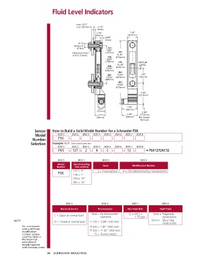
Sensor How to Build a Valid Model Number for a Schroeder FSK
Model BOX 1 BOX 2 BOX 3 BOX 4 BOX 5 BOX 6 BOX 7 BOX 8
Number FSK – – – – – – –
Selection Example: NOTE: One option per box
BOX 1 BOX 2 BOX 3 BOX 4 BOX 5 BOX 6 BOX 7 BOX 8
FKS – 127 – 2 – 4 – C – – 12 – = FSK12724C12
BOX 1 BOX 2 BOX 3 BOX 4
Model Size (mounting
Number hole centers) Seals Modification Number
127 = 5” 2 = Fluorocarbon 4 = FSK (determined by manufacturer)
FSK 176 = 7”
254 = 10”
381 = 15”
BOX 5 BOX 6 BOX 7 BOX 8
Electrical Switch Thermometer Hex Head Bolt Sight Tube
Omit = No thermometer 12 = M12 x Omit = Polyamide
C = Open at normal level
(standard) 1.75 bolt construction
NOTE: O = Closed at normal level FT 100 = 3.94” (100 mm) SO14 = Glass tube
construction
On instruments FT 200 = 7.87” (200 mm)
with a different FT 300 = 11.87” (300 mm)
modification
number, please TS = Thermo Switch
read the label or
the technical
amendment
details supplied
with the instrument.
90 SCHROEDER INDUSTRIES