
Page 88 - Schroeder - Accessories
P. 88
Electronic Temperature Switch
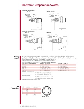
Operational scanning range:
280 mm 480 mm,1600 mm
Buttons
Buttons
51
84
Operational scanning range:
4000 mm 6400 mm
Buttons Buttons
Setting All of the terms and symbols used for setting the HNS 526 as well as the menu structure comply with the
Options specifications of the German Engineering Federation Standard (VDMA 24574-4) for level switches. In order to
prevent unauthorized adjustment of the device, a key-lock can be set.
Setting ranges of the switching points or switch-back points:
Switching Point Function Distance and Window Function Distance
Operating Scanning Range SP1, SP2, FH1, FH2* RP1, RP2, FL1, FL2*
280 mm 2-13 inch (2-32 cm) 1-12 inch (1-31 cm)
480 mm 2-23 inch (2-59 cm) 1-22 inch (1-58 cm)
1600 mm 2-71 inch (2-180 cm) 1-70 inch (1-179 cm)
4000 mm 2-183 inch (2-465 cm) 1-182 inch (1-464 cm)
6400 mm 2-291 inch (2-740 cm) 1-290 inch (1-739 cm)
Switching Point Function:
SP1, SP2 = Switching points 1 or 2
RP1, RP2 = Switch-back points 1 or 2
Window Function:
FH1, FH2 = Upper switch values 1 or 2
FL1, FL2 = Lower Switch values 1 or 2
*The increment for all devices is 1 cm or 1 inch.
Pin Pin HNS 526-2 HNS 526-3
Connections 1 +U B +U B
2 SP 2 I/U
3 O V O V
4 SP 1 SP 1
M12x1, 4 pole
86 SCHROEDER INDUSTRIES