
Page 93 - Schroeder - Accessories
P. 93
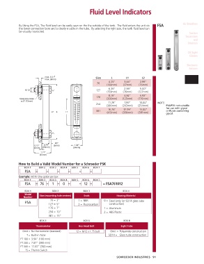
Fluid Level Indicators


            By Using the FSA, The fluid level can be easily seen on the the outside of the tank.  The fluid enters the unit via   FSA  Air Breathers
            the lower connection bore and is clearly vi-sable in the tube.  By selecting the right size, the tank fluid level can
            be visually monitored.
                                                                                                                   Suction
                                                                                                                Separators
                                                                                                                     and
                                                                                                                  Strainers

                                                                                                                  Oil Sight
                                                                                                                   Glasses


                                                                                                                 Electronic
                                                                                                                  Sensors

                            max. 0.31”                    Size      L        L1       L2                        Fluid Level
                            max. (8mm)
                                                                  4.25”     1.46”    2.99”                       Indicators
                                                           76
                                                                 (108mm)   (37mm)   (76mm)
                                                                  6.26”     2.99”    5.00”
                M 12                                       127
                                                                 (159mm)   (76mm)   (127mm)
                                                                  8.19”     4.92”    6.93”
                                                           176
             Clearance Hole                  HYDAC               (208mm)  (125mm)   (176mm)
              ø.51 (13mm)
                                             ºC    ºF             11.26”    7.99”    10.00”     NOTE:
                                              80-  -180    254
                                              70-  -160          (286mm)  (203mm)   (254mm)          FSA/FSK not suitable
                                              60-  -140                                              for use with glycol
                                              50-  -120           16.26”   12.99”    15.00”
                                L2  L   L1    40-  -100    381   (413mm)  (330mm)   (381mm)          or fluids containing
                                              30-  -80                                               glycol.
                                              20-  -60
                                              10-
                                              0-  -40
                                             -10-  -20

                                  20”
                      0.12”  0.79”  (5mm)     1.34”
                     (3mm)  (20mm)           (34mm)
                         1.77”
                         (45mm)

            How to Build a Valid Model Number for a Schroeder FSK
                BOX 1   BOX 2  BOX 3  BOX 4  BOX 5  BOX 6  BOX 7
                FSA   –      –      –     –      –     –
            Example: NOTE: One option per box
                BOX 1   BOX 2  BOX 3  BOX 4  BOX 5  BOX 6  BOX 7
                FSA   – 76 –    1   –  0  –      – 12 –        = FSA761012

                BOX 1           BOX 2              BOX 3                   BOX 4
                Model
               Number    Size (mounting hole centers)  Seals           Housing Material
                               76 = 3”          1 =  NBR       0 = Steel (only for SO14 glass tube
                FSA
                              127 = 5”          2 =  Fluorocarbon  construction)
                              176 = 7”                         1 = Aluminum
                              254 = 10”                        2 = ABS Plastic
                              381 = 15”
                         BOX 5                     BOX 6                   BOX 8
                      Thermometer               Hex Head Bolt             Sight Tube
               Omit = No thermometer (standard)  12 = M12 x 1.75 bolt  Omit = Polyamide construction
                 T = Built-in Tube                                SO14 = Glass tube construction
             FT 100 = 3.94” (100 mm)
             FT 200 = 7.87” (200 mm)
             FT 300 = 11.87” (300 mm)
                TS = Thermo Switch

                                                                       SCHROEDER INDUSTRIES   91