
Page 14 - Parker - Assembly/Installation
P. 14
4300 Catalog Assembly / Installation
Seal-Lok Assembly
Flanging Steps: 3. With the sleeve properly positioned within the die set,
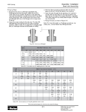
1. Determine the extra cut-off length required for the place the die set into the die holder of the machine.
Parflange process by referring to Tables S9 and S10. 4. Insert the tube through the die opening until it comes in
(Each table is only a guide. Variations in tube wall thick- contact with the tube stop. Do not forget to position the
ness and inconsistency in quality of tube cut-off may affect tube nut over the tube in the proper orientation, especially
actual dimensions. User should verify actual extra tube if the other tube end has already been flanged, or the tube
cut-off length with one or two flanges prior to large scale has sharp bends.
flanging.) 5. Flange the tube as shown in Figure S17.
2. Select the proper tooling for the tube size. The tube OD,
wall thickness and material must be known for proper Note: For more information on Parflange procedures, ma-
selection. Refer to Table R6 on page R24 for flanging capa- chines, etc., Contact Parker Tube Fittings Division.
bility by Parflange machine and availability of tooling
Fig. S18 – Extra cut-off length
Tube Tube Wall Thickness – Inch
O.D.
(in.) .028 .035 .049 .065 .083 .095 .109 .120 .134 .156 .188
1/4 3/16 13/64 7/32
3/8 5/32 3/16 13/64 15/64 1/4
1/2 9/64 9/64 3/16 13/64 9/32 19/64 19/64
5/8 11/64 3/16 13/64 1/4 17/64 17/64
3/4 11/64 3/16 7/32 7/32 1/4 17/64 9/32
1 3/16 3/16 13/64 15/64 1/4 19/64
1 1/4 11/64 3/16 13/64 15/64 1/4 19/64 19/64 21/64
1 1/2 13/64 15/64 15/64 1/4 17/64 19/64 23/64 3/8
Table S9 – Extra tube cut-off length guide for inch tube
Tube Metric Tube Outside Diameter – (mm)
O.D.
(in.) 6 8 10 12 16 20 25 30 38
3/16 7/32 1/8 5/32 9/64
1.0
5.2 5.7 3.1 4.1 3.6
17/64 15/64 13/64 7/32 11/64
1.5
6.7 5.9 5.1 5.4 4.2
13/64 15/64 3/16 7/32 15/64 17/64 9/32
2.0
5.3 6.1 4.9 5.4 6.1 6.6 7.2
17/64 7/32 15/64 1/4 19/64
2.5
6.7 5.5 6.1 6.4 7.6
15/64 17/64 9/32 5/16 19/64
3.0
5.8 6.7 7.2 7.9 7.7
17/64 19/64 21/64
3.5
6.9 7.5 8.5
9/32 5/16 11/32 11/32
4.0
7.2 8.0 8.6 8.7
11/32 3/8
5.0
8.8 9.4
Table S10 – Extra tube cut-off length guide for metric tube
Dimensions and pressures for reference only, subject to change.
S14 Parker Hannifin Corporation
Tube Fittings Division
Columbus, Ohio
http://www.parker.com/tfd