
Page 16 - Parker - Assembly/Installation
P. 16
4300 Catalog Assembly / Installation
Seal-Lok Assembly
Over-flanging will result in tube nut interference, as well as thin- Brazing
ning of the flange tube end. Under-flanging reduces the contact
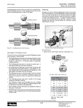
area for sealing against the O-ring in the fitting. Brazing is the other method of attaching the sleeve to the tube
end. This process can be accomplished by using a multi-flame
torch, as shown in Fig. S22, or an induction brazing unit. (Note:
multi-flame torches and induction brazing units are not available
through Tube Fittings Division). During the heating process,
the pre-formed braze ring or wire-fed filler material is melted
Overflanged assembly between the tube O.D. and the sleeve I.D., creating a strong
bond between the two.
Underflanged assembly
Fig. S21 – Overflanging and Underflanging Fig. S22 – Multi-flame torch brazing
Brazing Steps:
1. Determine the tube length allowance using Table S13.
Advantages of Parflange process
There are numerous advantages to using the Parflange process
over the braze or weld process:
• The Parflange process is several times faster than the brazing
or welding methods. For instance, the 1025 model produce
flanges at a rate of 9 to 12 times the speed of comparable
induction brazing.
• The Parflange process does not require any special pre- or
post-flange cleaning of the tube and sleeve.
• Unlike brazing, the Parflange process does not require any
flux, braze alloy, post braze cleaner or rust inhibitor. An en-
vironmentally safe lubricant applied to the flanging pin is the
only additive associated with the Parflange.
• The Parflange process is inherently safe. It does not require
open flame or any form of heating. Additionally, there is no Fig. S23 – Tube length allowance
emission of hazardous fumes, as is typical with welding and
brazing. Nominal Tube O.D.
A
• The Parflange process uses only a fraction of the energy Inch Metric (in.)
needed for welding or brazing.
• The Parflange process accommodates the use of plated 1/4 6 0.04
components (i.e., tube and sleeve), thus eliminating the need 3/8 8, 10 0.04
to electroplate assemblies after fabrication.
1/2 12 0.04
• The Parflange process eliminates the potential for leaks at
the braze or weld joint. 5/8 14, 15, 16 0.06
• The Parflange process produces a burnished sealing surface, 3/4 18, 20 0.06
typically much smoother than the 125 micro-inch requirement 1 22, 25 0.06
of SAE J1453.
1 1/4 28, 30, 32 0.06
1 1/2 35, 38 0.06
Table S13 – Tube length
allowance
Dimensions and pressures for reference only, subject to change.
S16 Parker Hannifin Corporation
Tube Fittings Division
Columbus, Ohio
http://www.parker.com/tfd