
Page 21 - Parker - Assembly/Installation
P. 21
4300 Catalog Assembly / Installation
Triple-Lok Assembly
joint tightness or clamping load. Therefore, it is recommended
to use this method wherever possible, and especially where the
plating combination of components is not known, and during
maintenance and repair where the components may be oily. Use
Table S18 as a guide for proper tightening method.
Condition Recommended Tightening Method
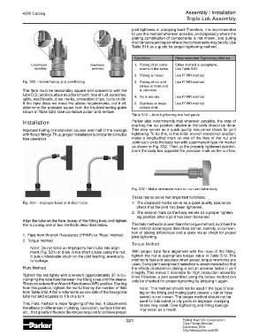
Underflared Overflared 1. Plating of all comp- Either method is acceptable.
assembly assembly onents is the same. Use Table S20.
2. Plating is mixed. Use FFWR method.
Fig. S30 – Underflaring and overflaring 3. Plating of nut and Use FFWR method.
sleeve or hose end
The flare must be reasonably square and concentric with the is unknown.
tube O.D.; and its surface must be smooth, free of rust, scratches, 4. Parts are oily. Use FFWR method.
splits, weld beads, draw marks, embedded chips, burrs or dirt.
If the flare does not meet the above requirements, cut it off, 5. Stainless or brass Use FFWR method.
determine the probable cause from the troubleshooting guide components.
shown in Table S20, take corrective action and re-flare.
Table S18 – Joint tightening method guide
Installation Parker also recommends that wherever possible, the step of
marking the nut position relative to the body should be done.
Improper flaring or installation causes over half of the leakage This step serves as a quick quality assurance check for joint
with flared fittings. Thus, proper installation is critical for a trouble tightening. To do this, at the initial wrench resistance position,
free operation. make a longitudinal mark on one of the flats of the nut and
continue it on to the body hex with a permanent type ink marker
as shown in Fig. S32. Then, at the properly tightened position,
mark the body hex opposite the previous mark on the nut hex.
Fig. S32 – Make reference mark on nut and tube body
These marks serve two important functions:
Fig. S31 – Improper bend and short tube 1. The displaced marks serve as a quick quality assurance
check that the joint has been tightened.
2. The second mark on the body serves as a proper tighten-
ing position after a joint has been loosened.
Align the tube on the flare (nose) of the fitting body and tighten
the nut using one of two methods described below. The flats method is slower than the torque method, but it has the
two distinct advantages described earlier, namely, circumven-
tion of plating differences and a quick visual check for proper
1. Flats from Wrench Resistance (FFWR) or “Flats” method joint tightening.
2. Torque method
Torque Method
Note: Do not force an improperly bent tube into align-
ment (Fig. S31) or draw-in too short a tube using the nut. With proper tube flare alignment with the nose of the fitting,
It puts undesirable strain on the joint leading, eventually, tighten the nut to appropriate torque value in Table S19. This
to leakage. method is fast and accurate when preset torque wrenches are
used. Consistent component selection is recommended so that
Flats Method the effects of dissimilar plating is not an adverse factor in joint
integrity. This makes it desirable for high production assembly
Tighten the nut lightly with a wrench (approximately 30 in.lb.), lines. However, a joint assembled using the torque method can
clamping the tube flare between the fitting nose and the sleeve. only be checked for proper tightening by torquing it again.
This is considered the Wrench Resistance (WR) position. Starting
from this position, tighten the nut further by the number of flats Note: This method should not be used if the type of plat-
from Table S18. A flat is referred to as one side of the hexagonal ing on the fitting and mating parts (sleeve + nut or hose
tube nut and equates to 1/6 of a turn. swivel) is not known. The torque method should not be
used for lubricated or oily parts as improper clamping
This Flats method is more forgiving of the two. It circumvents forces may result. Over-tightening and fitting damage
the effects of differences in plating, lubrication, surface finishes, may occur as a result.
etc., that greatly influence the torque required to achieve proper
S21 Parker Hannifin Corporation
Tube Fittings Division
Columbus, Ohio
http://www.parker.com/tfd