
Page 24 - Parker - Assembly/Installation
P. 24
4300 Catalog Assembly / Installation
Ferulok Assembly
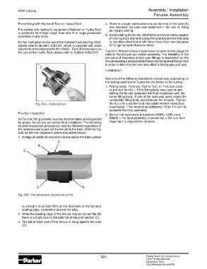
Pre-setting with Hyferset Tool or Hydra-Tool 4. There is a slight indentation around the end of the tube (E)
that indicates the tube was bottomed in the tool or fitting
Pre-setting with hydraulic equipment (Hyferset or Hydra-Tool) during pre-setting.
is preferred for fittings larger than size 8 or large production
quantities in any sizes. 5. Avoid rotating the ferrule. Steel ferrules should not be capable
of moving back and forth along the tube beyond the bite area
For full instruction on the use of the Hyferset Tool (see Fig. S34), (a stainless steel ferrule will move more than steel because
please refer to Bulletin 4393-B1, which is included with each of it’s spring back characteristics).
shipment of the Hyferset Kit #611049C. For full instructions on
the use of the Hydra-Tool, please refer to Bulletin 4392-B10. Caution: Wrench torque should never be used as the gauge for
reliable Ferulok pre-set and/or assembly. The reliability of the
pre-set and assembly of bite type fittings is dependent on the
ferrule traveling a prescribed distance into the tapered fitting throat
in order to bite into the tube and effect a strong grip and seal.
Installation
Use one of the following installation procedures, depending on
the tooling used earlier to pre-set the ferrule to the tubing.
1. Fitting body, Hyferset, Hydra-Tool, or Ferulset used
to pre-set ferrule – If the fitting body was used for pre-
setting the ferrule, complete the final installation with the
same fitting body. If one of the tools was used, select the
compatible fitting body and lubricate the threads. Tighten
Fig. S34 – Hyferset tool the nut until a sudden and noticeable wrench resistance
is achieved. Then wrench an additional 1/6 to 1/4 turn to
complete the final assembly.
Pre-Set Inspection 2. Swivel nut assembly procedure (R6BU, C6BU and
All Ferulok fitting presets must be disassembled and inspected S6BU) – For final assembly of swivel nut, a 3/4 turn from
for proper ferrule pre-set before final installation. The following finger tight is required for all sizes.
detailed inspection procedures must be followed regardless of
the method used to pre-set the ferrule to the tube. (Refer to Fig.
S35 for the five inspection points discussed below).
1. A ridge of metal (A) has been raised above the tube surface
C
B
E
A D
Fig. S35 – Ferulok preset inspection points
to a height of at least 50% of the thickness of the ferrule’s
leading edge, completely around the tube.
2. While the leading edge of the ferrule may be coined flat (B)
there is a slight bow to the balance of the pilot section (C).
3. The tail or back end of the ferrule is snug against the tube
(D).
S24 Parker Hannifin Corporation
Tube Fittings Division
Columbus, Ohio
http://www.parker.com/tfd