
Page 23 - Parker - Assembly/Installation
P. 23
4300 Catalog Assembly / Installation
Ferulok Assembly
Ferulok Assembly
Ferulok fitting assembly consists of the following steps:
1) Cutting, deburring and cleaning of the tube
2) Ferrule pre-set
3) Pre-set inspection
4) Final installation
Step 1 (cutting, deburring and cleaning of the tube) has been
previously covered (see page S12).
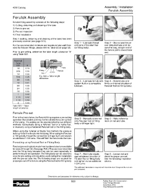
Step 1 – Lubricate thread Step 2 – Slip nut and ferrule
For the recommended minimum and maximum tube wall thick- and cone of Ferulset Tool over deburred tube end. Be
ness for Ferulok fittings, please refer to Table U3 on page U3. (or fitting body). sure the long, straight end of
the ferrule points toward tube
Prior to pre-setting, determine the tube length allowance “A” end.
using Table S21.
Nominal
Tube
O.D. A
1/8 0.19
3/16 0.23
1/4 0.23
5/16 0.25 Fig. S33 — Tube length
allowance
3/8 0.25 Step 3 – Lubricate ferrule with Step 4 – Bottom tube end
1/2 0.31 system fluid or a compatible firmly on internal shoulder of
5/8 0.35 lubricant. Ferulset Tool (or fitting body).
3/4 0.35
7/8 0.35
1 0.42
1 1/4 0.42
1 1/2 0.49
2 0.49
Table S21 — Tube
length allowance
Ferrule Pre-set
Prior to final installation, the Ferulok fitting requires a pre-setting Step 5 – Manually screw nut Step 6 – Make reference
operation that creates a bite by the ferrule into the outer surface onto Ferulset Tool or fitting mark on nut and tube.
of the tubing. Pre-setting can be accomplished by two different body until finger tight.
methods: hydraulically using a Hyferset Tool or a Hydra-Tool,
or manually using a hardened Ferulset tool or the fitting body.
When using the Hyferset or Hydra-Tool method, the pressure
build-up “bites” the ferrule into the tubing. When using the Ferulset
or fitting body, thread the connection to finger tight and wrench
an additional 1-3/4 turns. This will “bite” the ferrule into the tube.
Pre-setting using Ferulset Tool or Fitting Body
Ferulset pre-setting tools made from hardened steel are available
for sizes 2 through 32. (See page R36.) They are recommended
over the fitting body because they can be used repeatedly to
perform the pre-set operation. The fitting body can be used only Step 7 – Hold tube steady Step 8 – Loosen nut and
once for pre-setting and should be used during final installation against internal shoulder of check for proper pre-set.
with the pre-set tube line. The following steps are required for Ferulset Tool or fitting body Use the following inspection
proper pre-set of the ferrule using the Ferulset tool or fitting body. and tighten nut an additional criteria.
1-3/4 turns.
*No additional lubrication is required with stainless steel fittings as the nuts are
pre-lubricated.
Dimensions and pressures for reference only, subject to change.
S23 Parker Hannifin Corporation
Tube Fittings Division
Columbus, Ohio
http://www.parker.com/tfd