
Page 2 - Parker - Load and Motor Control Valves
P. 2
Catalog HY15-3502/US
Technical Tips Load and Motor Control Valves
CV
Introduction
Counterbalance valves are one of the most misunderstood products in the hydraulic industry. Many people tend to
complicate the task of selecting a counterbalance valve and as such avoid opportunities. The goal of this Technical
Valves
Check
Tips Section is to hopefully eliminate some of this confusion and help you chose the correct valve for your applica-
SH
tion. It is only a guide! It is not meant to be your only method of input, nor is it meant to replace good hydraulic
common sense and reasoning.
Shuttle
Valves
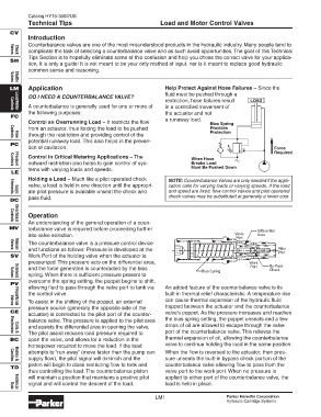
LM Application Help Protect Against Hose Failures – Since the
fluid must be pushed through a
DO I NEED A COUNTERBALANCE VALVE?
restriction, hose failures result LOAD
A counterbalance is generally used for one or more of in a controlled movement of
Controls
Load/Motor
the following purposes: the actuator and not
FC
Control an Overrunning Load – It restricts the flow a runaway load. Bias Spring
from an actuator, thus forcing the load to be pushed Provides
Protection
through the restriction and providing control of the
Flow
Controls
potential runaway load. This also helps in the preven-
PC
tion of cavitation. Force
Required
Control in Critical Metering Applications – The When Hose
outward restriction also helps to gain control of sys- Breaks Load
Must Be Pushed Down
Controls
Pressure
tems with varying loads and speeds.
LE
Holding a Load – Much like a pilot operated check NOTE: Counterbalance Valves are only needed if the appli-
valve, a load is held in one direction until the appropri- cation calls for varying loads or varying speeds. If the load
ate pilot pressure is available unseat the check and and speed are fixed, flow control valves and pilot operated
Logic
Elements
pass fluid. check valves may be substituted at generally a lower cost.
DC
Operation
An understanding of the general operation of a coun-
Controls
Directional
MV terbalance valve is required before proceeding further Differential
into valve selection. Valve Area
Port
The counterbalance valve is a pressure control device
and functions as follows: Pressure is developed at the Pilot
Manual
Valves
Port
SV Work Port of the holding valve when the actuator is
pressurized. This pressure acts on the differential area, Work By-Pass
and the force generated is counteracted by the bias Port Check
Bias Spring
spring. When there is sufficient pressure present to
Valves
Solenoid
overcome the spring setting, the poppet begins to shift,
PV
allowing fluid to pass through the valve port to tank via An added feature of the counterbalance valve is its
the control valve. built-in thermal relief characteristic. A temperature rise
To assist in the shifting of the poppet, an external can cause thermal expansion of the hydraulic fluid
Proportional
Valves
pressure source (generally the opposite side of the trapped between the actuator and the counterbalance
CE valve’s poppet. As the pressure increases and reaches
actuator) is connected to the pilot port of the counter-
balance valve. This pressure is applied to the pilot area the bias spring setting, the poppet unseats and a few
and assists the differential area in opening the valve. drops of oil are allowed to escape through the valve
The pilot assist reduces load pressure required to port of the counterbalance valve. This relieves the
Electronics
Coils &
BC open the valve, and allows for a reduction in the thermal expansion of oil, allowing the counterbalance
horsepower required to move the load. If the load valve to continue holding the load in the same position.
attempts to “run away” (move faster than the pump can When the flow is reversed to the actuator, then pres-
supply flow), the pilot signal will diminish and the sure unseats the built-in bypass check portion of the
Cavities
Bodies &
piston will begin to close restricting flow to tank and counterbalance valve allowing flow to pass from the
TD
thus controlling the load. The counterbalance piston valve port to the work port. When no pressure is
will maintain a position that maintains a positive pilot applied to either port of the counterbalance valve, the
signal and will control the descent of the load. load is held in place.
Technical
Data
LM1 Parker Hannifin Corporation
Hydraulic Cartridge Systems