Page 4 - Parker - Load and Motor Control Valves
P. 4

Catalog HY15-3502/US
                   Technical Tips                                    Load and Motor Control Valves

            CV
                   Selection Options (Continued)                       Thermal Setting – Counterbalance valves have a
                                                                       built-in thermal relief valve that compensates for the
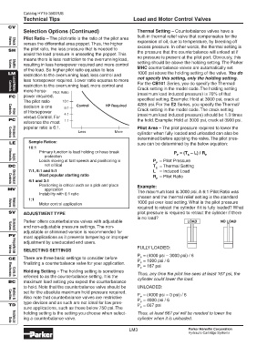
                   Pilot Ratio – The pilot ratio is the ratio of the pilot area
                                                                       expansion of oil, due to temperature, by bleeding off
                   versus the differential area poppet. Thus, the higher
            Valves
                                                                       excess pressure. In other words, the thermal setting is
              Check
            SH     the pilot ratio, the less pressure that is needed to  the pressure that the counterbalance will unload at if
                   assist the load pressure in unseating the poppet. This
                                                                       no pressure is present at the pilot port. Obviously, this
                   means there is less restriction to the overrunning load,
                                                                       setting should be above the holding setting. The Parker
                   resulting in less horsepower required and more control
                                                                       MHC counterbalance valves are automatically set
                   of the load. So higher pilot ratio equates to less
            Valves
              Shuttle
            LM                                                         1000 psi above the holding setting of the valve. You do
                   restriction to the overrunning load, less control and
                                                                       not specify this setting, only the holding setting.
                   less horsepower required. Lower ratio equates to more
                                                                       For the CB101 Series, you do specify the Thermal/
                   restriction to the overrunning load, more control and
                                                                       Crack setting in the model code. The holding setting
                   more horse-  Pilot Ratio
            Controls
              Load/Motor
            FC     power required.                                     (maximum load induced pressure) is 70% of that
                   The pilot ratio   10:1                              specified setting. Example: Hold at 3000 psi, crack at
                   decision is one    6:1  Control       HP Required   4285 psi. For the E2 Series, you specify the Thermal/
                   of Horsepower                                       Crack setting in the model code. The crack setting
                                      4:1                              (maximum load induced pressure) should be 1.3 times
            Controls
              Flow
                   versus Control. For
            PC                        1:1                              the hold. Example: Hold at 3000 psi, crack at 3900 psi.
                   reference the most
                   popular ratio is 6:1.                               Pilot Area – The pilot pressure required to lower the
                                            Less             More
                                                                       cylinder when fully loaded and unloaded can also be
                                                                       determined before applying the valve. The pilot pres-
              Pressure
            Controls
            LE       Sample Ratios:                                    sure can be determined by the below equation:
                     10:1
                          Primary function is load holding or hose break                P  = (T  – L) / R
                             protection                                                  P    S       P
                          Loads moving at fast speeds and positioning is      P = Pilot Pressure
            Elements
              Logic
                                                                                P
            DC               not critical                                     T = Thermal Setting
                                                                                S
                     7:1, 6:1 and 5:1                                         L = Induced Load
                          Most popular starting ratio                         R = Pilot Ratio
                     4:1 and 3:1                                                P
                          Positioning is critical such as a pick and place  Example:
            Controls
              Directional
            MV               application
                          Instability with 6:1 ratio                   The maximum load is 3000 psi. A 6:1 Pilot Ratio was
                                                                       chosen and the thermal relief setting is the standard
                     1:1
                          Motor control application                    1000 psi over load setting. What is the pilot pressure
                                                                       required to retract the cylinder if it is fully loaded? What
              Manual
            Valves
            SV     ADJUSTMENT TYPE                                     pilot pressure is required to retract the cylinder if there
                                                                       is no load?
                   Parker offers counterbalance valves with adjustable                        LOAD           NO LOAD
                   and non-adjustable pressure settings. The non-
                   adjustable or shimmed version is recommended for
            Valves
              Solenoid
            PV
                   most applications as it prevents tampering or improper
                   adjustment by uneducated end users.
                                                                       FULLY LOADED:
                   SELECTING SETTINGS
              Proportional
            Valves
                                                                       P  = (4000 psi – 3000 psi) / 6
                                                                         P
            CE     There are three basic settings to consider before   P  = 1000 psi / 6
                   finalizing a counterbalance valve for your application.  P
                                                                       P  = 167 psi
                                                                         P
                   Holding Setting – The holding setting is sometimes
                                                                       Thus, any time the pilot line sees at least 167 psi, the
                   referred to as the counterbalance setting. It is the
            Electronics
              Coils &
                                                                       cylinder could lower the load.
            BC     maximum load setting you expect the counterbalance
                   to hold. Note that the counterbalance valve should be  UNLOADED:
                   set for the absolute maximum hold pressure required.
                                                                       P  = (4000 psi – 0 psi) / 6
                   Also note that counterbalance valves are restrictive  P
                                                                       P  = 4000 psi / 6
            Cavities
              Bodies &
                   type devices and as such are not ideal for low pres-  P
            TD                                                         P  = 667 psi
                   sure applications, such as those below 750 psi. The   P
                   holding setting is the setting you choose when select-  Thus, at least 667 psi will be needed to lower the
                   ing a counterbalance valve.                         cylinder when it is unloaded.
              Technical
            Data
                                                                   LM3                         Parker Hannifin Corporation
                                                                                               Hydraulic Cartridge Systems
   1   2   3   4   5   6   7   8   9