Page 5 - Parker - Load and Motor Control Valves
P. 5

Catalog HY15-3502/US
                   Technical Tips                                    Load and Motor Control Valves

                                                                                                                           CV
                   Motor Controls                                      movement of the motor prior to the release of the
                                                                       brake, an equal area ratio counterbalance is used. To
                   Counterbalance valves are used in motor circuits to
                                                                       demonstrate let’s look again at the above example with  Check  Valves
                   stop overrunning loads and prevent cavitation. Since
                                                                       a 10:1 Ratio Counterbalance valve installed and a
                   hydraulic motors leak internally, the counterbalance                                                    SH
                                                                       maximum thermal setting of 3000 psi.
                   valve by itself cannot be used to hold the load. So, a
                   mechanical brake is used to hold the load on the motor  10:1 Example
                   in place, as shown below. Some typical applications                                                       Shuttle  Valves
                                                                          NO LOAD
                   include winches, swing drives, conveyor control and
                   traction drives. For applications in closed loop motor     P  = (T  – L) / R                            LM
                                                                                P    S       P
                   circuits, vented spring cavities are required.             P  = (3000 psi – 0 psi) / 10
                                                                                P                                            Load/Motor
                                                                              P  = 3000 psi / 10                              Controls
                                                                                P
                   Operation                                                  P  = 300 psi
                                                                                P
                   Free flow to the motor is allowed through the internal                                                  FC
                                                                          2000 PSI LOAD
                   check valve. In the controlled flow direction, the oil
                   passes across a metering poppet. The position of the       P  = (T  – L) / R P                             Controls
                                                                                     S
                                                                                P
                   metering poppet is determined by an external pilot         P  = (3000 psi – 2000 psi) / 10                Flow
                                                                                P
                   signal from the other side of the motor. In an open loop   P  = 1000 psi / 10                           PC
                                                                                P
                   motor circuit, this pilot signal will be a 1:1 ratio. The  P  = 100 psi
                                                                                P
                   reason an equal ratio pilot signal is utilized is to
                                                                       Thus, when there is no load on the motor, the counter-  Pressure  Controls
                   provide positive control as well as to release mechani-
                                                                       balance opens at 300 psi, or just as the brake is being
                   cal brakes (when used in a braking circuit). In applica-
                                                                       released. When there is a 2000 psi load on the motor,
                   tions where the motor will see overrunning loads in                                                     LE
                                                                       the counterbalance will start to open with a pilot
                   both directions (such as a traction drive circuit), a dual
                                                                       pressure of 100 psi. The brake requires 300 psi, so the
                   MMB or two single MMB valves must be used.                                                                 Elements
                                                                       motor can start to rotate before the brake is released,  Logic
                                                                       causing wear on the brake. To offset this problem, you
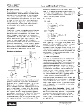
                   Brake Applications
                                                                       could increase the maximum thermal setting to 5000  DC
                                                       300 PSI
                                                                       psi, but this is very inefficient.                    Directional
                                                                       1:1 (Equal Area) Example                               Controls
                                                          Mechanical
                                                          Brake        Equal area counterbalance valves are used primarily  MV
                                                                       in brake applications to avoid the wear problem
                                                                       described above. With an Equal Area counterbalance
                                                                       valve, there is no thermal relief valve, and there is no  Manual  Valves
                                                                       differential area to work on. In other words, the coun-
                                                                                                                           SV
                                                                       terbalance valve only opens when the pilot pressure is
                                                                       greater than the valve setting. The applied load has
                                                                       nothing to do with the pilot pressure required. Thus you  Solenoid  Valves
                                                                       will want to choose a pressure setting for the equal
                                                                       area counterbalance valve that is just slightly above  PV
                                                                       the brake release pressure (usually 350 psi).
                                          LOAD        2000 PSI                                                               Proportional
                                                                       In our example, the valve would be set at 350 psi. This  Valves
                                                                       would allow the brake to release before the counterbal-
                   When the directional control valve is shifted, hydraulic
                                                                       ance allows the load to move. Since the equal counter-  CE
                   pressure (usually 300 psi) releases the mechanical
                                                                       balance  valve always opens at 350 psi pilot pressure
                   brake and allows the load to be moved. The counter-
                                                                       and is not dependent on the load, it is the best valve  Electronics
                   balance valve needs to provide adequate back pres-                                                        Coils &
                                                                       for brake applications.
                   sure to open the brake, then immediately counterbal-
                   ance the load. Ideally, the brake will be disengaged  Large Pressure Spike Application – Keep in mind   BC
                   before the motor begins to rotate. If this sequence is  that equal area counterbalance valves do not have a
                   not achieved, the motor will try to rotate against the  built-in thermal relief valve. As such, if there are large  Bodies &  Cavities
                   applied brake reducing the life of the brake. This would  pressure spikes caused by the stopping of heavy
                   be the equivalent of trying to drive with your emer-  loads, then a ratioed counterbalance, such as a 10:1  TD
                   gency brake applied.  Remember that hydraulic motors  should be used. In most cases these are non-brake
                                                                                                                             Technical  Data
                   are equal area devices. So, in an effort to avoid the  type applications.
                                                                   LM4                         Parker Hannifin Corporation
                                                                                               Hydraulic Cartridge Systems
   1   2   3   4   5   6   7   8   9   10