
Page 6 - Parker - Load and Motor Control Valves
P. 6
Catalog HY15-3502/US Counterbalance Valve
Technical Information Series CB101
CV
General Description
Cartridge Style Counterbalance Valve.
For additional information see Technical Tips
Check
Valves
SH on pages LM1-LM4.
Features
Shuttle
Valves
LM • Sealed spool type design for improved stability and
accuracy as well as low leakage
• Low leakage poppet-type check valve for reliable load
holding
Controls
Load/Motor
• All external parts have yellow zinc dichromate finish. Pilot
FC (3)
• Parker cartridge design for ease of installation and
maintenance (2) Valve
(2)
• Compact size for reduced space requirements
Controls
Flow
(3)
PC
Cylinder
(1)
(1)
Controls
Pressure
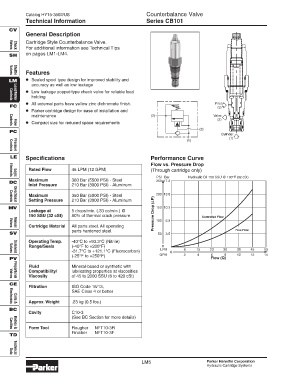
LE Specifications Performance Curve
Flow vs. Pressure Drop
Rated Flow 45 LPM (12 GPM) (Through cartridge only)
PSI Bar Hydraulic Oil 150 SSU @ 100°F (32 cSt)
Elements
Logic
Maximum 380 Bar (5500 PSI) - Steel 250 17.2
DC
Inlet Pressure 210 Bar (3000 PSI) - Aluminum
Maximum 350 Bar (5000 PSI) - Steel 200 13.8
Setting Pressure 210 Bar (3000 PSI) - Aluminum P)
Directional
Controls
MV 150 10.3
Leakage at 5 drops/min. (.33 cc/min.) @
150 SSU (32 cSt) 80% of thermal crack pressure Pressure Drop ( 100 6.9 Controlled Flow
Cartridge Material All parts steel. All operating
Manual
Valves
parts hardened steel. Free Flow
SV 50 3.5
Operating Temp. -40°C to +93.3°C (Nitrile)
Range/Seals (-40°F to +200°F) 0
LPM 8 15 23 30 38 45 53
-31.7°C to +121.1°C (Fluorocarbon) 0
Solenoid
Valves
(-25°F to +250°F) GPM 2 4 6 8 10 12 14
PV Flow (Q)
Fluid Mineral-based or synthetic with
Compatibility/ lubricating properties at viscosities
Viscosity of 45 to 2000 SSU (6 to 420 cSt)
Valves
Proportional
CE
Filtration ISO Code 16/13,
SAE Class 4 or better
Approx. Weight .23 kg (0.5 lbs.)
Coils &
Electronics
BC
Cavity C10-3
(See BC Section for more details)
Form Tool Rougher NFT10-3R
Cavities
Bodies &
Finisher NFT10-3F
TD
Technical
Data
LM5 Parker Hannifin Corporation
Hydraulic Cartridge Systems