
Page 226 - Wago_PCB_TerminalBlocksConnectors_Volume2_2015_US
P. 226
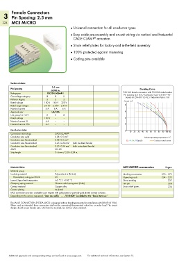
Female Connectors
   3 Pin Spacing: 2.5 mm
   224 MCS MICRO
                                              ●  Universal connection for all conductor types

                                              ●  Easy cable pre-assembly and on-unit wiring via vertical and horizontal
                                                CAGE CLAMP  actuation
                                                             ®
                                              ●  Strain relief plates for factory and in-the-field assembly

                                              ● 100% protected against mismating
                                              ●  Coding pins available


        Technical data:

        Pin Spacing               2.5 mm                                                   Derating Curve
                                  0.098 in.
        Ratings per            IEC/EN 60664-1                                   733-102 female connector with 733-332 male header
                                                                                Pin spacing: 2.5 mm / Conductor size: 0.5 mm  “f-st”
                                                                                                           2
        Overvoltage category   III  III   II                                     Based on: EN 60512-5-2 / Reduction factor: 0.8
        Pollution degree       3    2     2                                     Current in A
        Rated voltage        100 V  160 V  320 V
        Rated surge voltage  2.5 kV  2.5 kV  2.5 kV                              8
        Nominal current       6 A   6 A  6 A
        Approvals per             UL/CSA                                         6
        Use group UL 1059      B    C     D
        Rated voltage        150 V  –     –                                      4
        Nominal current UL    4 A   –     –
        Nominal current CSA   4 A   –     –                                      2
        Conductor data:                                                          0  10  20  30  40  50  60  70  80  90 100105
        Connection technology       CAGE CLAMP ®
        Conductor size: solid       0.08–0.5 mm 2                                            Ambient operating temperature in °C
        Conductor size: fine-stranded  0.08–0.5 mm 2                              2-, 4-, 6-, 12-pole  Conductor rated current
        Conductor size: fine-stranded  0.25–0.34 mm 2  (with insulated ferrule)
        Conductor size: fine-stranded  0.25–0.34 mm 2  (with uninsulated ferrule)
        AWG                         28–20
        Strip length                5–6 mm / 0.20–0.24 in.


        Material data:                                                          MCS MICRO accessories:     Pages:
        Material group              I
        Insulating material         Polyamide 6.6 (PA 6.6)                      Marking accessories     570 – 573
          Flammability rating per UL 94  0V                                     Operating tools         234 – 235
        Lower/Upper limit temperature  -60 °C / +100 °C                         Direct marking               237
        Clamping spring material    Chrome nickel spring steel (CrNi)           Test pin                     568
        Contact material            Copper alloy                                Strain relief plates         236
        Contact plating             tin-plated
        MCS connectors are also available upon request with gold-plated or partially gold-plated contact surfaces.
        Depending on the version requested, “item no. suffix    . . . /010-000” is added to the “basic item no.”

        The MULTI CONNECTION SYSTEM (MCS) is designed without breaking capacity for compliance with DIN EN 61984.
        When used as intended, these connectors shall not be connected/disconnected when live or under load. The circuit
        design should ensure header pins, which can be touched, are not live when unmated.


       Additional approvals and corresponding ratings can be found at www.wago.com.   For additional technical information, see Section 13.