Page 229 - Wago_PCB_TerminalBlocksConnectors_Volume2_2015_US
P. 229

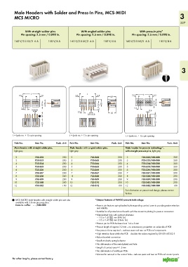
Male Headers with Solder and Press-In Pins, MCS-MIDI
          MCS MICRO                                                                                                3
                                                                                                                   227


                 With straight solder pins          With angled solder pins              With press-in pins*
              Pin spacing: 2.5 mm / 0.098 in.    Pin spacing: 2.5 mm / 0.098 in.     Pin spacing: 2.5 mm / 0.098 in.

          160 V/2.5 kV/2  6 A  150 V/4 A     160 V/2.5 kV/2  6 A   150 V/4 A    160 V/2.5 kV/2  4 A   150 V/4 A


                                                                                                                    3


                <_______ L _______>                <_______ L _______>               2,5  <______L ______>  2,5
                           2,5
                                                               2,5
             2,5
             __>  <    >  <__                    2,5  <    >  <__    <_8,9_>        __>   >    >    __>  >
                                                 __>
                            3,9 <  <7,8_>                       3,9  <  < 7,8_>                    3,9 <  <7,8 _  _
               2,5          >  _                                3,7  _                2,5          <
               __>  <                                                                 __>  >   0,6
                                                  2,5
                            <                     __>  <  0,8 x 0,8 >  >  <_8,1_>            >   __>  >
                       <
                     0,8x0,8 >
                                                           <
                         1  4,6
                            <_ 8,9 _>                                                               <_8,9_> 3,2
         L = (pole no. + 1) x pin spacing    L = (pole no. + 1) x pin spacing    L = (pole no. + 1) x pin spacing

          Pole No.     Item No.      Pack. Unit  Pole No.  Item No.     Pack. Unit  Pole No.  Item No.     Pack. Unit
          Male header with straight solder pins,   Male header with angled solder pins,   Male header for press-in technology*,
          light gray                         light gray                         with straight press-in pins, light gray
           2           733-332           200   2          733-362           200   2        733-332/100-000     200
           3           733-333           200   3          733-363           200   3        733-333/100-000     200
           4           733-334           200   4          733-364           200   4        733-334/100-000     200
           5           733-335           200   5          733-365           200   5        733-335/100-000     200
           6           733-336           200   6          733-366           200   6        733-336/100-000     200
           7           733-337           200   7          733-367           200   7        733-337/100-000     200
           8           733-338           200    8         733-368           200   8        733-338/100-000     200
           9           733-339           200   9          733-369           200   9        733-339/100-000     200
          10           733-340           200  10          733-370           200  10        733-340/100-000     200
          12           733-342           100  12          733-372           100  12        733-342/100-000     100
                                                                                For information on press-in tool design, please contact
                                                                                factory.
         1  MCS MICRO male headers with straight solder pins are also   *Unique features of WAGO press-in technology:
           available with 3.8 mm pin projection.
           Item no. suffix:    . . . /046-000                • Press-in pin features spring-loaded style expanding contact zone to provide greater retention
                                                              and stability
                                                             • Suitable for all printed circuit boards with the correct tin plating for press-in connectors
                                                             • Metal-plated hole with optimum diameter
                                                              – 1.0 or 1.45   mm (HAL Sn)
                                                              – 1.0 or 1.45 –0.00  mm (Chem. Sn)
                                                             • Press-in pin for PCB thickness from 1.4 to 3 mm
                                                             • Press-in length of approx 3.2 mm — no unnecessary projection on underside of PCB
                                                             • low press-in force required — reduces wear and tear on PCB and components
                                                             • High retention force within the PCB — doubles the values required by DIN EN 60352-5
                                                             • Robust bonded connection
                                                             • Excellent elastic spring behavior
                                                             • No deformation of the metal-plated end hole
                                                             • Length of contact area ≥ 1.3 mm
                                                             • No deformation of multilayer PCBs
                                                             • Minimal tin removal in the contact hole — reduces wear and tear on PCB and contact points
         For other lengths, please contact factory.
   224   225   226   227   228   229   230   231   232   233   234