Page 233 - Wago_PCB_TerminalBlocksConnectors_Volume2_2015_US
P. 233

THR (Through-Hole Reflow) Soldering Process
                                                                                                                   3

                                                                                                                   231


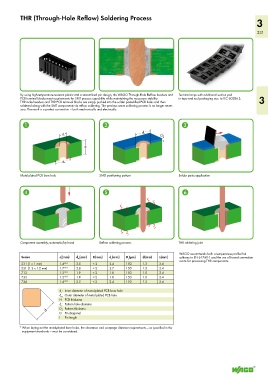
          By using high-temperature-resistant plastic and a streamlined pin design, the WAGO Through-Hole Reflow headers and   Terminal strips with additional suction pad
          PCB terminal blocks meet requirements for SMT process capability while maintaining the necessary stability.   in tape-and-reel packaging acc. to IEC 60286-3,  3
          THR male headers and THR PCB terminal blocks are simply pushed into the solder paste-filled PCB holes and then
          soldered along with the SMT components via reflow soldering. The previous wave soldering process is no longer neces-
          sary. The result is a perfect connection — both mechanically and electrically.


           1                                   2                                  3
                                                                 ______>
                              _>                                ______>  d s
                             d i                                         D s  <__
                            _>
                                       ______>                           <
                                        H  ______>

                              ______>
                             d A
                             _______>
          Metal-plated PCB bore hole         SMD positioning pattern            Solder paste application


           4                                   5                                  6


          Component assembly, automatic/by hand  Reflow soldering process       THR soldering joint


                                                                                 WAGO recommends both a temperature profile that
          Series            d(mm)   d (mm)   H(mm)   d (mm)   D (μm)   d(mm)   L(mm)  adheres to EN 61760-1 and the use of forced convection
                                                          s
                                                  s
                            i
                                    A
                                                                                 ovens for processing THR components.
          231 (1 x 1 mm)    1.4 +0.1    2.5   < 2   2.4   150   1.2     2.4
          231 (1.2 x 1.2 mm)  1.7 +0.1    2.8   < 2   2.7   150   1.5   2.4
          713               1.2 +0.1    1.9   < 2   1.8   150   1.0     2.4
          733               1.2 +0.1    1.9   < 2   1.8   150   1.0     2.4
          734               1.4 +0.1    2.5   < 2   2.4   150   1.2     2.4

                            d:  Inner diameter of metal-plated PCB bore hole
                            i
                            d :  Outer diameter of metal-plated PCB hole
                            A
                            H  PCB thickness
                  <____________ d___________>  D :  Pattern thickness
                            d :  Pattern hole diameter
                            s
                            s
                            D  Pin diagonal
                            L  Pin length
          *  When laying out the metal-plated bore holes, the clearance and creepage distance requirements — as specified in the
           equipment standards — must be considered.
   228   229   230   231   232   233   234   235   236   237   238