
Page 228 - Wago_PCB_TerminalBlocksConnectors_Volume2_2015_US
P. 228
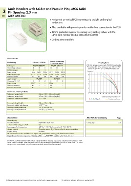
Male Headers with Solder and Press-In Pins, MCS-MIDI
   3 Pin Spacing: 2.5 mm
   226 MCS MICRO
                                              ●  Horizontal or vertical PCB mounting via straight and angled
                                                solder pins
                                              ●  Also available with press-in pins for solder-free connection to the PCB

                                              ●  100 % protected against mismating; only mating halves with the
                                                same pole number can be connected together
                                              ●  Coding pins available


        Technical data:
                                              Press-In Technology
        Pin Spacing            2.5 mm / 0.098 in.                                          Derating Curve
                                               2.5 mm / 0.098 in.
        Ratings per            IEC/EN 60664-1   IEC/EN 60664-1                  733-102 female connector with 733-362 male header
                                                                                Pin spacing: 2.5 mm / Conductor size: 0.5 mm  “f-st”
                                                                                                           2
        Overvoltage category   III  III   II   III  III   II                     Based on: EN 60512-5-2 / Reduction factor: 0.8
        Pollution degree       3    2     2    3    2     2                     Current in A
        Rated voltage         80 V  160 V  320 V  80 V  160 V  320 V
        Rated surge voltage  2.5 kV  2.5 kV  2.5 kV  2.5 kV  2.5 kV  2.5 kV      8
        Nominal current       6 A   6 A  6 A  4 A   4 A  4 A
        Approvals per             UL/CSA          UL/CSA                         6
        Use group UL 1059      B    C     D    B    C     D
        Rated voltage        150 V  –     –   150 V  –    –                      4
        Nominal current UL    4 A   –     –   4 A   –     –
        Nominal current CSA   4 A   –     –   4 A   –     –                      2
        Solder and press-in pin data:
        Solder pin: length/width    4.6 mm / 0.8 x 0.8 mm (straight)             0  10  20  30  40  50  60  70  80  90 100105
        Solder pin: length/width    3.7 mm / 0.8 x 0.8 mm (angled)                           Ambient operating temperature in °C
        Solder pin: drilled hole diameter  1.1 +0.1  mm                           2-, 4-, 6-, 12-pole  Conductor rated current

        Press-in pin: length/width   3.2 mm / 0.6 x 1.2 mm
        Press-in pin: drilled hole diameter  1.15 ±0.025  mm

        Press-in pin: metal-plated hole  1.0       mm (HAL Sn)
        Press-in pin: metal-plated hole  1.0 –0.00 mm (Chem. Sn)


        Material data:                                                          MCS MICRO accessory        Page:
        Material group              I
        Insulating material         Polyamide 6.6 (PA 6.6)                      Coding keys                  235
          Flammability rating per UL 94  0V
        Lower/Upper limit temperature  -60 °C / +100 °C / Press-in pin: -40 °C / +85 °C
        Contact material            Electrolytic copper (E ) / Copper alloy for press-in technology
                                                Cu
        Contact plating             tin-plated
        MCS connectors are also available upon request with gold-plated or partially gold-plated contact surfaces.
        Depending on the version requested, “item no. suffix    . . . /010-000” is added to the “basic item no.”

        The MULTI CONNECTION SYSTEM (MCS) is designed without breaking capacity for compliance with DIN EN 61984.
        When used as intended, these connectors shall not be connected/disconnected when live or under load. The circuit
        design should ensure header pins, which can be touched, are not live when unmated.


       Additional approvals and corresponding ratings can be found at www.wago.com.   For additional technical information, see Section 13.