
Page 373 - Wago_PCB_TerminalBlocksConnectors_Volume2_2015_US
P. 373
"
Female Connectors
MCS MIDI Classic 6
371
With integrated end plate
Pin spacing: 5 mm / 0.197 in. Pin spacing: 5 mm / 0.197 in.
0.08–2.5 mm 2 28–12 AWG 0.08–2.5 mm 2 28–12 AWG
320 V/4 kV/2 16 A 300 V/15 A 320 V/4 kV/2 16 A 300 V/15 A
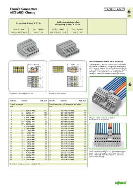
Group arrangement without loss of pin spacing
<_ ____ 26,45 _____> <____26,45 ___> Combining WAGO MULTI CONNECTION SYSTEM mul-
tipole female connectors into a single, long male header is
<_14,3_> <_14,3_> often a common customer request. This is made possible by
using modular female connectors with integrated end plate,
offering the possibility of side-by-side stacking without
needing an unused pole between connectors for spacing.
<_
<______L______> <_____ L _____> 6
5 5 <_
1,5 <_ _
_)
L = (pole no. x pin spacing) +1.5 mm L = pole no. x pin spacing
Pole No. Item No. Pack. Unit Pole No. Item No. Pack. Unit
Female connector, Female connector with integrated end plate,
gray gray
2 231-102/026-000 100 2 231-102/102-000 100
3 231-103/026-000 100 3 231-103/102-000 100
4 231-104/026-000 100 4 231-104/102-000 100
5 231-105/026-000 100 5 231-105/102-000 100 Total pole number for female connectors
6 231-106/026-000 50 6 231-106/102-000 50 = Pole number for male header
7 231-107/026-000 50 7 231-107/102-000 50
8 231-108/026-000 50 8 231-108/102-000 50
9 231-109/026-000 50 9 231-109/102-000 50
10 231-110/026-000 50 10 231-110/102-000 50
11 231-111/026-000 25 11 231-111/102-000 25
12 231-112/026-000 25 12 231-112/102-000 25
13 231-113/026-000 25 13 231-113/102-000 25
14 231-114/026-000 25 14 231-114/102-000 25
15 231-115/026-000 25 15 231-115/102-000 25
16 231-116/026-000 25 16 231-116/102-000 25
17 231-117/026-000 25 17 231-117/102-000 25
18 231-118/026-000 25 18 231-118/102-000 25
19 231-119/026-000 10 19 231-119/102-000 10
20 231-120/026-000 10 20 231-120/102-000 10 Female connectors with built-in end plate require no extra
21 231-121/026-000 10 21 231-121/102-000 10 space, while maintaining the nominal cross-section. This
22 231-122/026-000 10 22 231-122/102-000 10 means: Total length of female connectors is reduced to
23 231-123/026-000 10 23 231-123/102-000 10 “pole no. x pin spacing”!
24 231-124/026-000 10 24 231-124/102-000 10
2- to 3-pole female connectors – one latch only