
Page 376 - Wago_PCB_TerminalBlocksConnectors_Volume2_2015_US
P. 376
Female Connectors
6 MCS MIDI Classic
374
With integrated end plate
Pin spacing: 5.08 mm / 0.2 in. Pin spacing: 5.08 mm / 0.2 in.
0.08–2.5 mm 2 28–12 AWG 0.08–2.5 mm 2 28–12 AWG
320 V/4 kV/2 16 A 300 V/15 A 320 V/4 kV/2 16 A 300 V/15 A
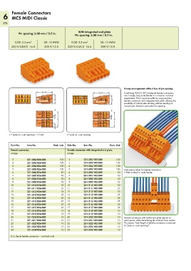
Group arrangement without loss of pin spacing
<_____ 26,45_____> <_____26,45 ____> Combining WAGO MCS multipole female connectors
into a single, long male header is a common customer
<_14,3_> <_14,3_> requirement. This is made possible by using modular
female connectors with integrated end plate, offering the
possibility of side-by-side stacking without needing an
unused pole between connectors for spacing.
< <
5,08 ___> <______L______> 5,08 ___> <_____L______>
1,5 <_ _
_)
L = (pole no. x pin spacing) +1.5 mm L = pole no. x pin spacing
Pole No. Item No. Pack. Unit Pole No. Item No. Pack. Unit
Female connector, Female connector with integrated end plate,
orange orange
2 231-302/026-000 100 2 231-302/102-000 100
3 231-303/026-000 100 3 231-303/102-000 100
4 231-304/026-000 100 4 231-304/102-000 100
5 231-305/026-000 100 5 231-305/102-000 100 Total pole number for female connectors
6 231-306/026-000 50 6 231-306/102-000 50 = Pole number for male header
7 231-307/026-000 50 7 231-307/102-000 50
8 231-308/026-000 50 8 231-308/102-000 50
9 231-309/026-000 50 9 231-309/102-000 50
10 231-310/026-000 50 10 231-310/102-000 50
11 231-311/026-000 25 11 231-311/102-000 25
12 231-312/026-000 25 12 231-312/102-000 25
13 231-313/026-000 25 13 231-313/102-000 25
14 231-314/026-000 25 14 231-314/102-000 25
15 231-315/026-000 25 15 231-315/102-000 25
16 231-316/026-000 25 16 231-316/102-000 25
17 231-317/026-000 25 17 231-317/102-000 25
18 231-318/026-000 10 18 231-318/102-000 10
19 231-319/026-000 10 19 231-319/102-000 10
20 231-320/026-000 10 20 231-320/102-000 10 Female connectors with built-in end plate require no
21 231-321/026-000 10 21 231-321/102-000 10 extra space, while maintaining the nominal cross-section.
22 231-322/026-000 10 22 231-322/102-000 10 This means: Total length of female connectors is reduced
23 231-323/026-000 10 23 231-323/102-000 10 to “pole no. x pin spacing”!
24 231-324/026-000 10 24 231-324/102-000 10
2- to 3-pole female connectors – one latch only