
Page 610 - Wago_PCB_TerminalBlocksConnectors_Volume2_2015_US
P. 610
UL Specifications – Underwriters Laboratories USA (continued)
13 Tests and Testing Procedures per UL Standards (continued)
608
• Insulation Parameters per UL 1059
The table below shows the potential involved and the corresponding clearances and creepage distance required in the different
applications.
Minimum Acceptable Spacing for Terminal Blocks, UL Standard 1059, Table 8.1
Notes
Spacing in inches (mm) between uninsu-
lated live parts of opposite polarity, unin- 1 A slot, groove, or similar, 0.013 inches (0.33 mm)
wide or less in the contour of the insulating material is
sulated live parts and uninsulated to be disregarded.
grounded parts other than the enclosure 2 Air space of 0.013 inches (0.33 mm) or less between
a live part and an insulating surface is to be disre-
Use group Application Potential involved Through Over garded for the purpose of measuring over surface
in volts air surfaces spacing.
a The spacing between wiring terminals of opposite
51 – 150 1/2 (12.7) (19.1) polarity and the spacing between a wiring terminal
Dead-front switchboards, 3/4 and a grounded dead metal part may not be less
A panelboards, service equipment 151 – 300 3/4 (19.1) 1–1/4 (31.8) than 1/4 inch (6.4 mm) if short-circuiting or grounding
and similar applications 301 – 600 1 (25.4) 2 (50.8) of such terminals may result from projecting strands of
wire.
Commercial appliances, includ- 51 – 150 1/16 a (1,6) a 1/16 a (1.6) a b See Section 8.5 (UL 1059)
ing business equipment, elec- 151 – 300 3/32 a (2,4) a 3/32 a (2.4) a The spacing values indicated in sub-paragraph D in
B Table 8.1 are applicable to a terminal block for use
tronic data processing equip- 301 – 600 3/8 (9,5) 1/2 (12.7) only in or with industrial control equipment where the
ment and similar applications load on any single circuit of the terminal block does
not exceed
Industrial, general 51 – 150 1/8 a (3.2) a 1/4 (6.4) 15 A at 51–150 V, 10 A at 151–300 V,
C 151 – 300 1/4 (6.4) 3/8 (9.5) 5 A at 301–600 V
301 – 600 3/8 (9.5) 1/2 (12.7) or the maximum ampere rating, whichever is less.
c Applies only to terminal blocks investigated to Part II
Industrial, devices having 51 – 300 1/16 a (1.6) a 1/8 a (3.2) a of this standard. See Section 22.1 (UL 1059).
D
limited ratings 301 – 600 3/16 a (4.8) a 3/8 (9.5)
E Terminal blocks rated 601– 601 – 1000 0,55 (14.0) 0,85 (21.6)
1500 V c 1001 – 1500 0,70 (17.8) 1,20 (30.5)
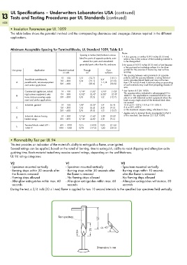
• Flammability Test per UL 94
This test provides an indication of the material‘s ability to extinguish a flame, once ignited.
Several ratings can be applied, based on the rated of burning, time to extinguish, ability to resist dripping and after-glow extin-
guishing time. Each material tested may receive several ratings, depending on the wall thickness.
UL 94 rating categories:
V2 V1 V0
- Specimen mounted vertically - Specimen mounted vertically - Specimen mounted vertically
- Burning stops within 30 seconds after - Burning stops within 30 seconds after - Burning stops within 10 seconds
the flame is removed the flame is removed after the flame is removed
- Flaming drips allowed - No flaming drips allowed - No flaming drips allowed
- After-glow extinguishes within max. 60 - After-glow extinguishes within max. 60 - After-glow extinguishes within max. 30
seconds seconds seconds
During the test, a 3/4 inch (20 ±1 mm) flame is applied for two 10 second intervals to the specified bar specimen held vertically.
125 ______>
Test specimen
_> <_____ ca. 45°
20
< 10 <_
<
Dimensions in mm