
Page 608 - Wago_PCB_TerminalBlocksConnectors_Volume2_2015_US
P. 608
UL Specifications – Underwriters Laboratories USA (continued)
13 Tests and Testing Procedures per UL Standards (continued)
606
• Heat Cycling Test per UL 1059, UL 486 E
Tests performed:
per UL 1059 per UL 486 E (equipment wiring terminals)
Test performed with maximum rated cross sectional area Test performed with maximum rated cross sectional area
Test current applied 150 % of the max. rated current Test current: increased test current per UL 486 E, Table 4
84 cycles of: 3 1/2 h “ON” / 1/2 h “OFF” 500 cycles of: 1 h “ON” / 1 h “OFF”
1 1/2 h “ON” / 1 1/2 h “OFF”
(from 4/0 AWG up to 400 kcmil per UL 486 E)
The temperature rises at the terminal blocks and control wires
The temperature rise is measured after the are measured and recorded after: 1, 25, 50, 75, 100, 125,
first and the 84th cycle. Cycle 175, 225, 275, 350, 425 and 500 cycles.
The temperature rise shall not exceed 125°C (257°F) and the
The temperature rise shall not exceed 5 °C (41 °F) after the stability factor “S” shall exceed ± 10.
84th cycle,
compared to the temperature measured after the first cycle.
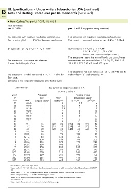
Conductor size Test current for copper conductors in A
UL 486 E, Table 4
AWG Assigned Heating cycling
or max. Static Temperature rating a
kcmil (mm ) ampere rating b heating a,c,g 75 °C d,g 90 °C e,g
2
30 (0.05) - 3 3.5 4
28 (0.08) - 3.5 4 5
26 (0.13) - 5.5 6 8
24 (0.20) - 7 8 10
22 (0.32) - 9 12 13
20 (0.52) - 12 16 17
18 (0.82) - 17 19 24
16 (1.3) - 18 20 31
14 (2.1) 15 [20] 30 [22] 33 [27] 40
12 (3.3) 20 [25] 35 [28] 39 [40] 54
10 (5.3) 30 [40] 50 [45] 56 [60] 75
8 (8.4) 50 70 80 100
6 (13.3) 65 95 105 131
4 (21.2) 85 125 140 175
3 (26.7) 100 145 165 205
2 (33.6) 115 170 190 240
1 (42.4) 130 195 220 275
1/0 (53.5) 150 230 255 320
2/0 (67.4) 175 265 300 370
3/0 (85.0) 200 310 345 435
4/0 (107) 230 360 405 505
250 (127) 255 405 445 565
300 (152) 285 445 500 625
a See Section 7.2, 8.2 and 9.2 (UL 486 E)
b Values are for 75 °C (167 °F), not more than 3 conductors in raceway or cable ampacities, National Electric Code, ANSI/NFPA
70.
c Values are for 75 °C (167 °F) single conductors in free air ampacities, National Electric Code, ANSI/NFPA 70.
d Values are approximately 112 % of the static heating test currents.
e Values for No. 8 AWG and larger conductors are approximately 140 % of the static heating test currents.
f See Section 9.2.4
g Values in parentheses apply to connectors with assigned ampere ratings.