
Page 236 - Parker - Parker Pneumatic
P. 236
Catalog PDN1000-3US Actuator Products – Rodless Cylinders
Parker Pneumatic P1X Series
Specifications
Model P1X (Standard w/switch)
Bore size mm (inch nominal) 16 (5/8) 20 (3/4), 25 (1) 32 (1-1/4), 40 (1-1/2) 50 (2), 63 (21/2)
Port size – N series M5 (10-32) 1/8 NPT 1/4 NPT 3/8 NPT
Port size – M series M5 (10-32) 1/8 Rc 1/4 Rc 3/8 Rc
Stroke tolerance in. ±0.080 to 39" ±0.100 to 118" ±0.120 to 196"
2-80 IPS with side ports on each end (Ø16 & Ø20 bores 2-40 IPS with single end porting with 39" stroke)
Piston speed, *in./sec.
(Ø25, Ø32, Ø40, Ø50 & Ø63 bores 2-40 IPS with single end porting with 78" stroke)
Cushion Air cushion standard
Lubrication Not required (if you choose to lubricate your system, continuing lubrication will be required.)
*Actual piston speed with one end port will vary depending on stroke length.
Weight & theoretical force characteristics B
Weights
Weight at zero stroke Weight per 1" Theoretical force (lbs)
Area M00 MLB MLB1 (25.4mm) stroke At pressure (PSI)
Bore in 2 lbs kg lbs kg lbs kg lbs kg 30 40 60 80 100
16 0.31 0.70 0.3 0.73 0.3 0.77 0.4 0.07 0.03 9 12 19 25 31 Rodless Cylinders Actuator Products
20 0.49 1.15 0.5 1.19 0.5 1.28 0.6 0.10 0.04 15 20 29 39 49
25 0.84 2.21 1.0 2.43 1.1 2.43 1.1 0.15 0.07 23 30 46 61 76
32 1.26 3.31 1.5 3.53 1.6 3.75 1.7 0.20 0.09 38 50 69 100 125
40 1.96 5.29 2.4 5.51 2.5 — — 0.27 0.12 59 78 117 156 195
50 3.08 7.94 3.6 8.16 3.7 — — 0.40 0.18 91 122 182 243 304
63 4.86 13.67 6.2 14.33 6.5 — — 0.63 0.28 145 193 290 386 483
OSP-P Series
Moments
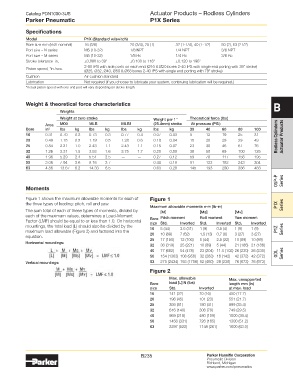
Figure 1 shows the maximum allowable moments for each of Figure 1
the three types of loading: pitch, roll and yaw. P1X
Maximum allowable moments n-m (lb-in) Series
The sum total of each of these types of moments, divided by [M] [Ms] [Mv]
each of the maximum values, determines a Load-Moment Pitch moment Roll moment Yaw moment
Factor (LMF) should be equal to or less than 1.0. On horizontal Bore Inverted Std. Inverted Std. Inverted
size Std.
mountings, the total load (L) should also be divided by the 5 (44) 3.5 (31) 1 (9) 0.5 (4) 1 (9) 1 (9)
maximum load allowable (Figure 2) and factored into the 16 P1Z Series
equation. 20 10 (89) 7 (62) 1.5 (13) 0.7 (6) 3 (27) 3 (27)
5 (44)
2.5 (22)
12 (106)
17 (150)
25
10 (89)
10 (89)
Horizontal mountings:
32 36 (319) 25 (221) 10 (89) 5 (44) 21 (186) 21 (186)
40 77 (682) 54 (478) 23 (204) 11.5 (102) 26 (230) 26 (230)
50 154 (1363) 108 (956) 32 (283) 16 (142) 42 (372) 42 (372) GDL Series
Vertical mountings: 63 275 (2434) 193 (1708) 52 (460) 26 (230) 76 (673) 76 (673)
Figure 2
Max. allowable Max. unsupported
Bore load [L] N (lbs) length mm (in)
size Std. Inverted at max. load
16 141 (32) 70 (16) 450 (17.7)
20 198 (45) 101 (23) 551 (21.7)
25 356 (81) 180 (41) 899 (35.4)
32 616 (140) 308 (70) 749 (29.5)
40 959 (218) 480 (109) 1000 (39.4)
50 1456 (331) 726 (165) 1300 (51.2)
63 2297 (522) 1148 (261) 1600 (63.0)
B235 Parker Hannifin Corporation
Pneumatic Division
Richland, Michigan
www.parker.com/pneumatics