
Page 249 - Parker - Parker Pneumatic
P. 249
Catalog PDN1000-3US Actuator Products – Rodless Cylinders
Parker Pneumatic P1Z Series - Basic Version
technical data
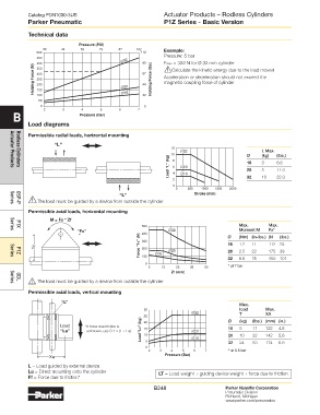
Pressure (PSI)
29 44 58 73 87 102 example:
500 112
450 Pressure: 5 bar
400 ∅32 90 Fmax = 322 N for Ø 32 mm cylinder
Holding Force (N) 300 ∅20 67 Holding Force (lbs) Acceleration or deceleration should not exceed the
350
!
Calculate the kinetic energy due to the load moved
250
magnetic coupling force of cylinder
44
200
150
100
50 ∅16 22
0 2 3 4 5 6 7 0
B Pressure (Bar)
load diagrams
Permissible radial loads, horizontal mounting
“l”
12
∅32 L Max.
10 8 Ø (kg) (lbs.)
Load "L" (kg) 6 4 ∅20 16 3 5 6.6
20
11.0
Actuator Products
Rodless Cylinders
2 ∅16 32 10 22.0
0
0 500 1000 1500 2000
“l” Stroke (mm)
! The load must be guided by a device from outside the cylinder
Series
OSP-P
Permissible axial loads, horizontal mounting
M = Fx * Zf
500 Max. Max.
“Fx” 400 ∅32 Ø Moment M Fx* (lbs.)
P1X
Series
Force "Fx" (N) 300 16 1.2 11 112 25
(Nm) (in-lbs.) (N
Zf 200 ∅16 ∅20 20 2.5 22 175 39
100
P1Z
Series
0 32 8.5 75 450 101
5 15 25 35 50 * at 7 bar
Zf (mm)
! The load must be guided by a device from outside the cylinder
GDL
Series
Permissible axial loads, vertical mounting
“L”
Max.
30 load Max.
∅32 T XA
25
Load * If force due friction is 20 Ø (kg) (lbs.) (mm) (in.)
“La” unknown, use 0.1 × (L + La). Load "LT" (kg) 15 ∅20 16 5 11 122 4.8
20
5.6
142
22
10
10
∅16
0 5 32 24 53 174 6.8
2 3 4 5 6 7 * at 6.5 bar
Xa Pressure (Bar)
l = Load guided by external device
la = Direct mounting onto the cylinder lt = Load weight + guiding device weight + force due to friction
Ff = Force due to friction*
B248 Parker Hannifin Corporation
Pneumatic Division
Richland, Michigan
www.parker.com/pneumatics