
Page 246 - Parker - Parker Pneumatic
P. 246
Catalog PDN1000-3US Actuator Products – Rodless Cylinders
Parker Pneumatic P1X Series
Positioning of stroke adjustment unit
ø16~ø25 ø32~ø63
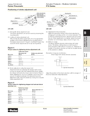
(1) Moving the stroke adjustment unit. (4) Adjustment of shock absorber. B
The stroke adjustment unit can be moved by loosening the Adjust the absorption energy of the shock absorber by
mounting bolts. changing the operating stroke of the shock absorber. This
(2) Locking of stroke adjustment unit. is done by loosening the shock absorber nut and turning
After moving the stroke adjustment unit to the appropriate the unit. When adjustment is complete, tighten the shock
position, lock it there by tightening the mounting bolts to absorber nut to the torque values shown in Figure 12a.
the torque values shown in Figure 4. Insufficient torque may (5) Notes on usage. Rodless Cylinders Actuator Products
cause the stroke adjustment unit to slip out of position. The shock absorber absorbs rated energy with rated
stroke. The factory setting allows a small amount of
shock absorber stroke before it bottoms out. Readjust the
Figure 4 location of the shock absorber so that the complete stroke
torque values for tightening stroke adjustment unit. of the absorber is utilized.
Tightening torque
Mounting bolt Stroke adj. plate bolt Absorption energy as set at factory:
Bore size (lb-in) (lb-in) Small margin with stroke of shock absorber. OSP-P Series
16mm 9-11 4-6
20mm 22-24
25mm 46-50 22-24
32mm 195-213 –
40mm 390-415 – P1X Series
50, 63mm 682-735 –
(3) Stroke adjustment using the stopper bolt. Cylinder Stroke End
Adjust the stroke by loosening the stopper bolt nut and P1Z Series
turning the stopper bolt. After adjusting the stroke, tighten
the stopper bolt nut to the torque values shown in Figure 5. Adjust the position of the shock absorber until the plunger of
When adjusting the 16-25 mm cylinders, due to the small the shock absorber is fully depressed.
amount of clearance between the table and the stroke
adjustment plate, adjust the stroke by moving the complete GDL Series
stroke adjustment unit.
Figure 5
torque values for tightening stopper bolt nut and shock
absorber nut. Cylinder Stroke End
Tightening torque
Stopper bolt nut Shock absorber nut
Bore size (lb-in) (lb-in)
16mm 10-11 12-16
20mm 22-24 26-35
25mm 73-84 40-53
32mm 195-213 66-89
40mm 390-425 195-266
50mm 682-735 487-620
63mm 1772-1914 487-620
B245 Parker Hannifin Corporation
Pneumatic Division
Richland, Michigan
www.parker.com/pneumatics