
Page 316 - Parker - Parker Pneumatic
P. 316
Catalog PDN1000-3US Automation Products – Slide Tables
Parker Pneumatic P5SS Slide Table Selection
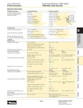
Selection Flow Chart
Operating conditions Formula and charts Selection example
List out the operating conditions Model used Cylinder: P5SS-6-10
according to mounting position and Cushion style Cushion: Cushion pad
shape of the workpiece
Workpiece install position Workpiece table mounting
Mounting position Mounting: Lateral mounting L1
Average speed Va (mm/s) Average speed: Va = 150mm/s
Allowable load W (kg) (Figure 1) Load: W = 0.3kg L2 + A5
Overhang Ln (mm) (Figure 2) L1 = 4mm
L2 = 4mm L3
L3 = 4mm
Kinetic energy
Calculate kinetic energy E(J) of work E = 1/2 • W (V/1000) 2 E = 1/2 • 0.3 ( 210/1000) 2 = 0.0066 B
Collision speed V = 1.4 • Va Collision speed V = 1.4 • 150 = 210
Calculate allowable kinetic energy Ea(J) Ea = K • Emax Ea = 1 • 0.015 = 0.015
Workpiece mounting coefficient K: Figure 3 Possible to use by E = 0.0066 ≤ Ea = 0.015
Make sure that kinetic energy of work is Max. allowable kinetic energy Emax: Table 1
less / lower than allowable kinetic energy. Kinetic energy (E) ≤ Allowable kinetic energy (Ea)
Load rate Automation Products Actuator Products
Load rate of work
Calculate static work Wa(kg) Wa = K • β • Wmax Wa = 1 x 1 x 0. = 0.66
Workpiece mounting coefficient K: Figure 3 K = 1
Allowable load coefficient β: Figure 4 β = 1
Maximum allowable moment Wmax: Table 2 Wmax = 0.6
Calculate load rate 1 of static work 1 = W/Wa 1 = 03/0.6 = 0.5
Load rate of static moment Yawing Rolling
Calculate static moment M(Nm). M = W x 9.8 (Ln + An)/1000 Calculate My Calculate Mr Grippers
Correction value for moment center My = W x 9.8 (L1 + A3)/1000 = Mr = W x 9.8 (L3 + A2)/1000 = 0.3
distance An: Table 3 0.3 x 9.8 (4 +13)/1000 = 0.05 x 9.8 (5 + 6)/1000 = 0.033
Calculate allowable static moment Ma(Nm). Ma = K • γ • Mmax A3 = 13 A2 = 6
Workpiece mounting coefficient K: Figure 3 May = 1 x 1 x 0.7 = 0.7 Mar = 0.7 (Same value as Ma) Slide Tables
Allowable moment coefficient γ : Figure 5 Mymax = 0.7
Max. allowable moment Mmax: Table 4 K = 1
Calculate load rate 2 of static moment 2 = M/Ma γ = 1
2 = 0.05/0.7 = 0.072 '2 = 0.033/0.7 = 0.047 Rotary Tables
Load rate of kinetic moment Pitching Yawing
Calculate kinetic moment Me(Nm). Me = 1/3 • We • 9.8 (Ln +An)/1000 Calculate Mep Calculate Mey
Collision equivalence load We = δ • W • V Mep = 1/3 x 2.52 x 9.8 x Mey = 1/3 x 2.52 x 9.8 x
(5 + 6)/1000 = 0.09 (4 + 16)/1000 = 0.165
δ: Cushion coefficient with cushion pad We = 4/100 x 0.3 x 210 = 2.52 We = 2.52
(Standard) = 4/100 with shock absorber = 1/100 Escapements
Calculate allowable kinetic moment Mea(Nm). Correction value for moment center A2 = 6 A4 = 16
distance An: Table 3
Mea = K γ Mmax Meap = 1 x 0.97 x 0.7 = 0.679 Meay = 0.679 (Same value as
Meap)
Workpiece mounting coefficient t K: Figure 3 K = 1
Allowable moment coefficient γ: Figure 5 γ = 0.97 Sensors
Max. allowable moment Mmax: Table 4 Mpmax = 0.
Calculate load rate 3 of kinetic moment. 3 = Me/Mea 3 = 0.09/0.679 = 0.13 '3 = 0.165/0.679 = 0.243
Sum of load rate
When sum of load rate does not exceed 1, it is ∑n = 1 + 2 + 3 ≤ 1 ∑n = 1 + 2 + '2 + 3 + '3 ≤ 1 Fittings
possible to use. = 0.5 + 0.072 + 0.047 + 0.133 + 0.243 = 0.995 ≤ 1
And it is possible to use.
B315 Parker Hannifin Corporation
Pneumatic Division
Richland, Michigan
www.parker.com/pneumatics