
Page 584 - Wago_Rail-MountedTerminalBlockSystems_Volume1_2015_US.pdf
P. 584
14 Tests and Testing Procedures per IEC/EN Standards (continued)
582 Mechanical Tests (continued)
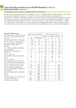
• Pull-Out Test to IEC/EN 60947-7-1, IEC/EN 60998-2-2, IEC/EN 60999-1
This test simulates the mechanical stress on the clamping unit when, for example, the installer pushes the conductor aside to better
access/operate the adjacent clamping unit, or verifies if the conductor is connected properly by briefly pulling on it.
During the test, a pulling force is applied without jerking, for one minute, to the connected conductor. The pulling force is selected
according to the cross-sectional area. The larger the cross section of the conductor, the higher the pull-out force that is selected.
For example, the pulling force is 40N for a conductor having a cross-section of 1.5mm² (AWG 16) and 100N for a conductor
with a cross-section of 16mm² (AWG 6). The values specified by the standard are the same for both screw-clamp and spring-
clamp terminal blocks. During the test, the conductor must neither slip out of the clamping unit, nor break near the clamping unit.
Conductor Pull-Out Forces Rated Cross-Sectional Area Pull-Out Forces per IEC/EN
The clamping units of screwless terminal
blocks must withstand the pull-out forces 60947-7-1 60998-2-2 60999-1/ -2
as follows: mm² AWG/kcmil N N N
IEC 60947-1/EN 60947-1/VDE 0660, 0.2 24 10 10 10
Part 100, Table 5: Low-voltage switch- 0.34 22 15 15 15
gear and controlgear - General rules 0.5 20 20 20 20
IEC 60947-7-1/EN 60947-7-1/ 0.75 18 30 30 30
VDE 0611, 1 – 35 35 35
Part 1: Rail-mounted terminal blocks for 1.5 16 40 40 40
copper conductors 2.5 14 50 50 50
IEC 60998-2-1/EN 60998-2-1/ 4 12 60 60 60
VDE 0613, 6 10 80 80 80
Part 2-1, Table 104 10 8 90 90 90
IEC 60998-2-2/ EN 60998-2-2/VDE 16 6 100 100 100
0613, 25 4 135 135 135
Part 2-2, Table 103: – 3 156
Connecting devices for low-voltage cir- 35 2 190 190 190
cuits for household and similar purposes. – 1 236
Particular requirements for connecting 50 1/0 236 236
devices as separate entities with screw- 70 2/0 285 285
clamp or screwless terminal blocks. 95 3/0 351 351
IEC 60999-1/EN 60999-1/VDE 0609,
–
Part 1, Table 3: 120 4/0 427 427
250
427
427
IEC 60999-2/EN 60999-2/VDE 0609,
Part 101, 150 300 427 427
350
503
503
185
Table 2:
Safety requirements for screw-clamp and – 400 503 503
screwless clamping units for 240 500 578 578
electrical copper conductors. 300 600 578 578