
Page 587 - Wago_Rail-MountedTerminalBlockSystems_Volume1_2015_US.pdf
P. 587
14
585
Since their inception, CAGE CLAMP and CAGE CLAMP S connections have been routinely tested for their resistance to shock/
®
®
vibration in connection with approval tests.
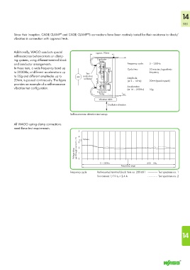
Additionally, WAGO conducts special approx. 90mm
self-resonance behavior tests on clamp-
ing systems, using different terminal block Conductor
fixing
and conductor arrangements. Frequency cycle: 5 – 250Hz
In these tests, a wide frequency band up Cycle time: 20 minutes, logarithmic
to 2000Hz, at different accelerations up Test frequency
to 20g and different amplitudes up to mV conductors Amplitude
20mm, is passed continuously. The figure soldered (at 5 – 16Hz): 20mm (peak-to-peak)
provides an example of a self-resonance
vibration test configuration. Acceleration 10g
(at 16 – 250Hz)
Conductor
fixing I test
Vibration table
Oscillation direction
Self-resonance vibration test set-up
All WAGO spring clamp connections
meet these test requirements.
5
4 3 3.2 Vmax.
Voltage drop per through contact in mV 2 1
0
5 – 250Hz 250 – 5Hz
Frequency range
Frequency cycle Rail-mounted terminal block: Item no. 280-681 -------------------- Test specimen no. 1
Test current: 1/10 I N = 2.4 A - - - - - - - - - Test specimen no. 2
14