
Page 281 - Mechatronics with Experiments
P. 281
October 28, 2014 11:15 254mm×178mm
Printer: Yet to Come
JWST499-c05
JWST499-Cetinkunt
ELECTRONIC COMPONENTS FOR MECHATRONIC SYSTEMS 267
V cc
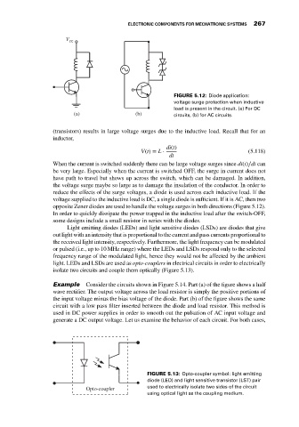
FIGURE 5.12: Diode application:
voltage surge protection when inductive
load is present in the circuit. (a) For DC
(a) (b) circuits, (b) for AC circuits.
(transistors) results in large voltage surges due to the inductive load. Recall that for an
inductor,
di(t)
V(t) = L ⋅ (5.118)
dt
When the current is switched suddenly there can be large voltage surges since di(t)∕dt can
be very large. Especially when the current is switched OFF, the surge in current does not
have path to travel but shows up across the switch, which can be damaged. In addition,
the voltage surge maybe so large as to damage the insulation of the conductor. In order to
reduce the effects of the surge voltages, a diode is used across each inductive load. If the
voltage supplied to the inductive load is DC, a single diode is sufficient. If it is AC, then two
opposite Zener diodes are used to handle the voltage surges in both directions (Figure 5.12).
In order to quickly dissipate the power trapped in the inductive load after the switch-OFF,
some designs include a small resistor in series with the diodes.
Light emitting diodes (LEDs) and light sensitive diodes (LSDs) are diodes that give
out light with an intensity that is proportional to the current and pass currents proportional to
the received light intensity, respectively. Furthermore, the light frequency can be modulated
or pulsed (i.e., up to 10 MHz range) where the LEDs and LSDs respond only to the selected
frequency range of the modulated light, hence they would not be affected by the ambient
light. LEDs and LSDs are used as opto-couplers in electrical circuits in order to electrically
isolate two circuits and couple them optically (Figure 5.13).
Example Consider the circuits shown in Figure 5.14. Part (a) of the figure shows a half
wave rectifier. The output voltage across the load resistor is simply the positive portions of
the input voltage minus the bias voltage of the diode. Part (b) of the figure shows the same
circuit with a low pass filter inserted between the diode and load resistor. This method is
used in DC power supplies in order to smooth out the pulsation of AC input voltage and
generate a DC output voltage. Let us examine the behavior of each circuit. For both cases,
FIGURE 5.13: Opto-coupler symbol: light emitting
diode (LED) and light sensitive transistor (LST) pair
Opto-coupler used to electrically isolate two sides of the circuit
using optical light as the coupling medium.