
Page 282 - Mechatronics with Experiments
P. 282
JWST499-Cetinkunt
JWST499-c05
268 MECHATRONICS Printer: Yet to Come October 28, 2014 11:15 254mm×178mm
V V Low pass
FB FB R filter
V (t)
out
V (t) R L V (t) C R L V (t)
in
out
in
(a) (b)
Input and output voltages vs time for parameters: RC = 0.1/60, R L C = 10.0/60
10
10
0
5
Voltage (V) 0 V out
–10 V in
10
0 –5
–10
–10
0 0.02 0.04 0.06 0.08 0 0.01 0.02 0.03 0.04 0.05 0.06 0.07
Time (s)
(c)
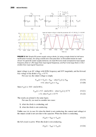
FIGURE 5.14: Simple DC power supply using a diode: (a) using a single diode for half wave
rectification function, (b) using a diode and a low pass filter. (c) Simulated results for each
circuit. For good DC power supply behavior, we need RC to be small compared to input signal
frequency (that is 1∕RC larger than input signal frequency), and R L C to be large (that is 1∕R L C
smaller than input signal frequency).
input voltage is an AC voltage with 60 Hz frequency and 10 V magnitude, and the forward
bias voltage of the diode is V FB = 0.7V.
For case (a), the output voltage is simply
V out (t) = V (t) − V FB : when V (t) ≥ V FB (5.119)
in
in
= 0; when V (t) < V FB (5.120)
in
Since V (t) = 10.0 ⋅ sin(2 60 t),
in
V out (t) = 9.3 ⋅ sin(2 60 t): when V (t) ≥ 0.7 V (5.121)
in
= 0; when V (t) < 0.7 V (5.122)
in
The results are plotted in the same figure.
For case (b), we need to consider two cases:
1. when the diode is conducting, and
2. when the diode is not conducting.
Unlike case (a), in case (b) when the diode is not conducting, the current (and voltage) at
the output circuit is not zero due to the capacitor. When the diode is conducting,
(V (t) − V ) ≥ V out (t) (5.123)
FB
in
the full circuit is active. When the diode is not conducting,
(V (t) − V ) < V out (t) (5.124)
in
FB