
Page 284 - Mechatronics with Experiments
P. 284
JWST499-Cetinkunt
JWST499-c05
270 MECHATRONICS Printer: Yet to Come October 28, 2014 11:15 254mm×178mm
which shows that in order to make the decay rather slow and obtain a DC output voltage,
R C should be as large as possible. R will be function of the load connected to the output,
L
L
therefore we have more control over the value of capacitor, C, to make sure that R C is
L
large enough to provide a smooth output DC voltage relative to the oscillation frequency
of the input voltage. Results are shown for 60 Hz input voltage and RC = 0.1∕60, R C =
L
10.0∕60.
In summary, the diode alone only passes the positive half of the input signal and acts
as a half wave rectifier. The diode plus the low pass filter circuit smooth out the oscillations
of the AC input and provide almost constant DC output voltage. In order to get a smooth
DC output voltage, the 1∕(RC) should be much larger than the input signal frequency
and 1∕(R C) should be much smaller than the input signal frequency. The performance
L
of the simple DC power supply shown in Figure 5.14b can be simulated for different
values of R ⋅ C and R ⋅ C relative to the frequency of the input signal which is 60 Hz in
L
this example.
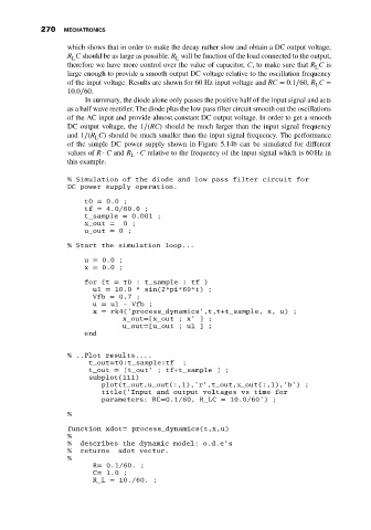
% Simulation of the diode and low pass filter circuit for
DC power supply operation.
t0 = 0.0 ;
tf = 4.0/60.0 ;
t_sample = 0.001 ;
x_out = 0;
u_out = 0;
% Start the simulation loop...
u = 0.0 ;
x = 0.0 ;
for (t = t0 : t_sample : tf )
u1 = 10.0 * sin(2*pi*60*t) ;
Vfb = 0.7 ;
u = u1 - Vfb ;
x = rk4(’process_dynamics’,t,t+t_sample, x, u) ;
x_out=[x_out ; x’ ] ;
u_out=[u_out ; u1 ] ;
end
% ..Plot results....
t_out=t0:t_sample:tf ;
t_out = [t_out’ ; tf+t_sample ] ;
subplot(111)
plot(t_out,u_out(:,1),’r’,t_out,x_out(:,1),’b’) ;
title(’Input and output voltages vs time for
parameters: RC=0.1/60, R_LC = 10.0/60’) ;
%
function xdot= process_dynamics(t,x,u)
%
% describes the dynamic model: o.d.e’s
% returns xdot vector.
%
R= 0.1/60. ;
C= 1.0 ;
R_L = 10./60. ;