
Page 35 - GuardII+ Series 4208 Platform EV User Manual
P. 35
Installation
• Sensors that are linked for multi-axis analysis must be connected on the same input
connector.
• The connections made on the EV card must match the settings in the configuration
(refer to Section 6.3.3).
Note:
The sensors may be connected before configuring the monitor, or the other
way around; whichever is more convenient.
Note:
Section 8.6 contains a template that can be used to record the connections
to make it easier to configure the EV card correctly.
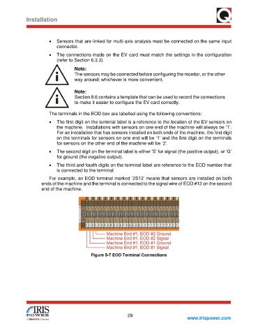
The terminals in the EOD box are labelled using the following conventions:
• The first digit on the terminal label is a reference to the location of the EV sensors on
the machine. Installations with sensors on one end of the machine will always be ‘1’.
For an installation that has sensors installed on both ends of the machine, the first digit
on the terminals for sensors on one end will be ‘1’ and the first digit on the terminals
for sensors on the other end of the machine will be ‘2’.
• The second digit on the terminal label is either ‘S’ for signal (the positive output), or ‘G’
for ground (the negative output).
• The third and fourth digits on the terminal label are reference to the EOD number that
is connected to the terminal.
For example, an EOD terminal marked ‘2S12’ means that sensors are installed on both
ends of the machine and the terminal is connected to the signal wire of EOD #12 on the second
end of the machine.
Figure 5-7 EOD Terminal Connections
29
www.irispower.com