
Page 36 - GuardII+ Series 4208 Platform EV User Manual
P. 36
Installation
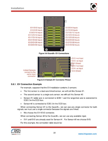
Figure 5-8 GuardII+ EV Connections
Figure 5-9 Sample EV Connector Pinout
5.8.1. EV Connection Example
For example, suppose that the EV installation contains 2 sensors:
• The first sensor is a dual-axis linked sensor; we will call this Sensor #1.
• The second sensor is a single-axis sensor; we will call this Sensor #2.
• Sensor #1 radial axis is connected to EOD 1 and the tangential axis is connected to
EOD 2 in the EOD box.
• Sensor #2 is connected to EOD 3 in the EOD box.
When connecting Sensor #1 to the GuardII+, we can use any single connector for both
signals; we must use a single connector because the signals are linked.
• We choose the EV1/EV2 connector.
When connecting Sensor #2 to the GuardII+, we can use any available input.
• EV1 and EV2 are already used for Sensor #1. For Sensor #2 we choose EV5.
For this example, the connection table would be:
30
www.irispower.com