
Page 9 - Georgia Markham
P. 9
7. Project 12: Redesign Cookworks Hand Mixer Designs
Exploded View
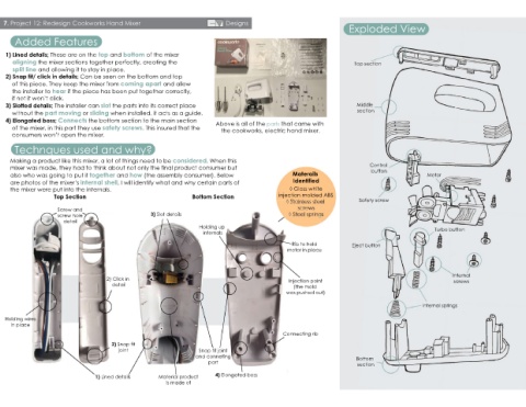
Added Features
1) Lined details; These are on the top and bottom of the mixer
aligning the mixer sections together perfectly, creating the Top section
split line and allowing it to stay in place.
2) Snap fit/ click in details; Can be seen on the bottom and top
of this piece. They keep the mixer from coming apart and allow
the installer to hear if the piece has been put together correctly,
if not it won’t click.
3) Slotted details; The installer can slot the parts into its correct place Middle
without the part moving or sliding when installed, it acts as a guide. section
4) Elongated boss; Connects the bottom section to the main section Above is all of the parts that came with
of the mixer, in this part they use safety screws. This insured that the the cookworks, electric hand mixer.
consumers won’t open the mixer.
Technques used and why?
Making a product like this mixer, a lot of things need to be considered. When this
mixer was made, they had to think about not only the final product consumer but Control
button
also who was going to put it together and how (the assembly consumer). Below Materails Motor
are photos of the mixer’s internal shell, I will identify what and why certain parts of Identified
the mixer were put into the internals. ◊ Gloss white
Top Section Bottom Section injection molded ABS
◊ Stainless steel Safety screw
Screw and screws
screw hole 3) Slot details ◊ Steel springs
detail
Holding up Turbo button
internals
Rib to hold Eject button
motor in place
Internal
2) Click in Injection point screws
detail (the mold
was pushed out)
Internal springs
Holding wires
in place
Connecting rib
2) Snap fit
joint Snap fit joint
and conneting Bottom
part
section
1) Lined details Material product 4) Elongated boss
is made of