
Page 17 - DP Vol 20 No 5_Neat
P. 17
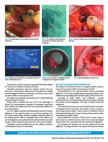
Fig 4: The abutment was removed for examination   Fig 5: The infected soft tissue was   Fig 6: The bone defect was circumferential to the
           of the site                              removed with erbium YAG laser   implant
                                                    treatment


           Fig 7: Implant decontamination proceeded with the   Fig 8: The bone graft comprised a mix of   Fig 9: Bone grafting was carried out
           Litetouch all-tissue laser                autograft and xenograft material

              The abutment was then removed to expose the infected site (Figure   IMPLANT SURFACE DECONTAMINATION
           4). There was no evidence of abutment fractures.        The setting on the Litetouch laser was changed to gentle treatment
              Treatment commenced using the Litetouch erbium YAG all-  mode, 40mJ per pulse at 20Hz and total power of 0.80W.
           tissue laser. The granulation tissue around the implant was carefully   Decontamination of the exposed implant surface commenced
           removed (Figure 5) with the machine set to soft tissue mode, 150mJ   (Figure 7). The machine’s gentle treatment package delivers a sub-
           per pulse at 20Hz and total power of 3W.                ablative low energy setting with selective targeting of the area of focus.
              The implant was checked to ensure there was no residual tethering   According to Shibli (2018): ‘Laser irradiation... removes
           of the granulation soft tissue.                         contaminates from the implant surface without damaging or altering
              Baudot (2017) concludes that one of the main advantages of   the titanium surface topography’. This helps to improve blood clot
           erbium YAG laser treatment compared to conventional approaches   stabilisation.
           is the ability to thoroughly remove all of the granulation tissue from   The Litetouch laser is easy to use and, because the entire mechanism
           peri-implant lesions.                                   is integrated into the hand piece, the machine is able to produce a
              The bone defect presented circumferentially around the implant   direct energy delivery system. There is almost no limitation of hand
           (Figure 6). It was noted that there was good blood pooling at the   movement, facilitating good access to all areas of the patient’s mouth,
           site. Good vascularisation indicated conditions were favourable for   particularly the posterior region.
           the  healing  process.  With an  unimpeded view  of the  implant  and   Bone grafting then took place. With the aid of a bone scraper, a
           surrounding tissue, we concluded that the outlook for the bone health   small amount of cortical bone was taken from around the implant
           was good, which meant our plan would be to try to save the implant.  site and mixed with a xenograft bovine-derived material (Figure 8).
              The patient was then consulted and was very relieved, wanting to   The  autograft  and xenograft  mix was  then  packed  into the  site
           avoid losing the implant if at all possible.            (Figure 9). A collagen membrane was placed, before primary closure


                         Access this article online at https://www.dental-practice.biz/emagazine/dp20-5/#p=16

                                                              Dental Practice I November-December 2024 I Vol 20 No 5  17