
Page 457 - NGTU_paper_withoutVideo
P. 457
Modern Geomatics Technologies and Applications
Figure 8: construction of a model of dam (Seep model) in FE software (left), forces acting on dam
(right)
Firstly, in Insitu analysis, the weight of dam is employed to achieve the initial
stresses and then, this initial stress is utilized in Load / Deformation analysis where
the water pressure can also be considered. In Appendix A and B, The material and
hyperbolic parameters of dam's embankment for initial stress analysis have been
shown.
To improve the accuracy, dam seepage analysis (SEEP Analysis) can be done before
this step, and then, the output table (PWP Table or Pore Water Pressure) is employed
for analysis of the next step. Due to that the reservoir has been filled gradually and
sometimes, the time needed to achieve the specified level of reservoir is more than
two years, the analysis could be performed on different levels of the reservoir. Then,
we could evaluate the effect of water level of reservoir on the results. Some of the
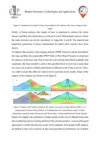
outputs of this analysis are shown in the figure 9.
Figure 9: Outputs of FE analysis related to the central cross section of dam (Section 260m): 1) X-
displacement for Elasto-Plastic Model, 2) Y-displacement for Linear-Elastic model, 3) Mesh
deformation caused by loads (Gravity Load & Water load), 4) Stress distribution for Insitu Analysis
Figure 10 compares the subsidence of target points on the crest of Masjed-Soleyman
dam resulted by precise leveling and from finite element analysis. A reasonably good
agreement is visible between the results of two methods. Four points in FE analysis
are linked to four cross sections of dam that geotechnical instruments are installed