
Page 63 - Shaping A Sustainable Future
P. 63
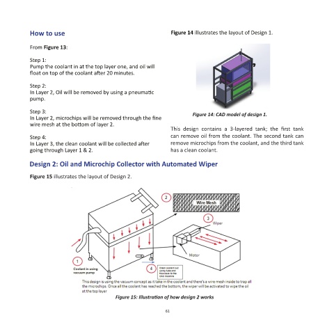
How to use                                           Figure 14 illustrates the layout of Design 1.


            From Figure 13:

            Step 1:
            Pump the coolant in at the top layer one, and oil will
            float on top of the coolant after 20 minutes.

            Step 2:
            In Layer 2, Oil will be removed by using a pneumatic
            pump.

            Step 3:                                                      Figure 14: CAD model of design 1.
            In Layer 2, microchips will be removed through the fine
            wire mesh at the bottom of layer 2.
                                                                 This  design  contains  a  3-layered  tank;  the  first  tank
            Step 4:                                              can remove oil from the coolant. The second tank can
            In Layer 3, the clean coolant will be collected after   remove microchips from the coolant, and the third tank
            going through Layer 1 & 2.                           has a clean coolant.

            Design 2: Oil and Microchip Collector with Automated Wiper

            Figure 15 illustrates the layout of Design 2.


                                            Figure 15: Illustration of how design 2 works


                                                               61