
Page 64 - Shaping A Sustainable Future
P. 64
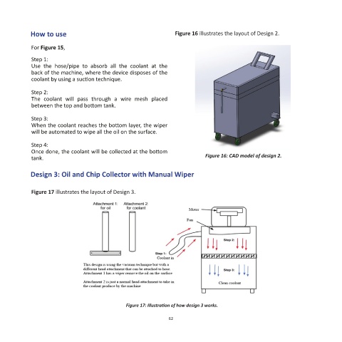
How to use                                           Figure 16 illustrates the layout of Design 2.


            For Figure 15,
            Step 1:
            Use  the  hose/pipe  to  absorb  all  the  coolant  at  the
            back of the machine, where the device disposes of the
            coolant by using a suction technique.

            Step 2:
            The  coolant  will  pass  through  a  wire  mesh  placed
            between the top and bottom tank.

            Step 3:
            When the coolant reaches the bottom layer, the wiper
            will be automated to wipe all the oil on the surface.

            Step 4:
            Once done, the coolant will be collected at the bottom
            tank.                                                           Figure 16: CAD model of design 2.

            Design 3: Oil and Chip Collector with Manual Wiper


            Figure 17 illustrates the layout of Design 3.


                                               Figure 17: Illustration of how design 3 works.

                                                               62