
Page 65 - Shaping A Sustainable Future
P. 65
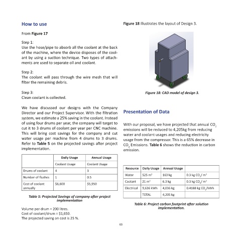
How to use                                           Figure 18 illustrates the layout of Design 3.


            From Figure 17

            Step 1:
            Use the hose/pipe to absorb all the coolant at the back
            of the machine, where the device disposes of the cool-
            ant by using a suction technique. Two types of attach-
            ments are used to separate oil and coolant.

            Step 2:
            The coolant will pass through the wire mesh that will
            filter the remaining debris.

            Step 3:                                                         Figure 18: CAD model of design 3.
            Clean coolant is collected.

            We  have  discussed  our  designs  with  the  Company
            Director and our Project Supervisor. With the filtration   Presentation of Data
            system, we estimate a 25% saving in the coolant. Instead
            of using four drums per year, the company will target to   With our proposal, we have projected that annual CO
            cut it to 3 drums of coolant per year per CNC machine.   emissions will be reduced to 4,205kg from reducing   2
            This  will  bring  cost  savings  for  the  company  and  cut   water and coolant usages and reducing electricity
            water  usage  per  machine  from  4  drums  to  3  drums.   usage from the compressor. This is a 65% decrease in
            Refer to Table 5 on the projected savings after project   CO  Emissions. Table 6 shows the reduction in carbon
                                                                   2
            implementation.                                      emission.
                                 Daily Usage    Annual Usage
                              Coolant Usage   Coolant Usage
                                                                  Resource  Daily Usage  Annual Usage
             Drums of coolant  4              3
                                                                  Water    525 m     163 kg       0.3 kg CO / m 3
                                                                               3
             Number of flushes  1             0.5                                                       2
                                                                  Coolant  21 m 3    6.3 kg       0.3 kg CO / m 3
             Cost of coolant   $6,600         $5,950                                                    2
             annually                                             Electrical  9,636 kWh  4,036 kg  0.4188 kg CO /kWh
                                                                                                           2
                Table 5: Projected Savings of company after project        TOTAL     4,205 kg
                              implementation
                                                                       Table 6: Project carbon footprint after solution
            Volume per drum = 200 litres.                                          implementation.
            Cost of coolant/drum = $1,650.
            The projected saving on cost is 25 %.
                                                               63