
Page 255 - Kitab3DsMax
P. 255
Chapter 7: Transforming Objects, Pivoting, Aligning, and Snapping
Transform Coordinate Center
The Transform Coordinate Center button uses the center of the Local Coordinate System. If the View
Coordinate System is selected, then all objects are transformed about the center of the viewport grid. If an
object is selected as the coordinate system using the Pick option, then all transformations are transformed
about that object’s center.
When you select the Local Coordinate System, the Use Transform Center button is ignored and objects are
transformed about their local axes. If you select multiple objects, then they all transform individually about
their local axes. Grouped objects transform about the group axes.
For example, the default pivot point for a Cylinder object is in the middle of the cylinder’s base, so if the
Transform Center is set to the Use Pivot Point option, then the cylinder rotates about its base pivot point. If
the Use Selection Center option is selected, then the cylinder rotates about its center point. If the Use
Transform Coordinate Center option is selected for the View Coordinate System, then the cylinder is
rotated about the grid origin.
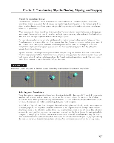
Figure 7.6 shows a simple cylinder object in the Left viewport using the different transform center modes.
The left image shows the Pivot Point Center mode, the middle image shows the Selection Center mode with
both objects selected, and the right image shows the Transform Coordinate Center mode. For each mode,
notice that the Rotate Gizmo is located at different locations.
FIGURE 7.6
The Rotate Gizmo is located in different places, depending on the selected Transform Center mode.
Selecting Axis Constraints
Three-dimensional space consists of three basic directions defined by three axes: X, Y, and Z. If you were to
stand on each axis and look at a scene, you would see three separate planes: the XY plane, the YZ plane,
and the ZX plane. These planes show only two dimensions at a time and restrict any transformations to the
two axes. These planes are visible from the Top, Left, and Front viewports.
By default, the Top, Left, and Front viewports show only a single plane and thereby restrict transformations
to that single plane. The Top view constrains movement to the XY plane, the Left or Right side view con-
strains movement to the YZ plane, and the Front view constrains movement to the ZX plane. This setting is
adequate for most modeling purposes, but sometimes you might need to limit the transformations in all the
viewports to a single plane. In Max, you can restrict movement to specific transform axes using the Restrict
Axes buttons in the Axis Constraints toolbar. You access this toolbar, shown in Figure 7.7, by right-clicking
the main toolbar (away from the buttons) and selecting Axis Constraints options from the pop-up menu.
207
6/30/10 4:15 PM
13_617779-ch07.indd 207
13_617779-ch07.indd 207 6/30/10 4:15 PM