
Page 403 - Kitab3DsMax
P. 403
Chapter 13: Modeling with Polygons and Patches
Cross-Ref
The Soft Selection rollout allows you to alter adjacent nonselected subobjects when selected subobjects are
moved, creating a smooth transition. For the details on this rollout, see Chapter 10, “Accessing Subobjects and
Using Modeling Helpers.” n
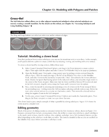
FIGURE 13.4
The Ring and Loop buttons can select an entire row and/or column of edges.
Tutorial: Modeling a clown head
Now that you know how to select subobjects, you can use the transform tools to move them. In this example,
you’ll quickly deform a sphere to create a clown face by selecting, moving, and working with some vertices.
To create a clown head by moving vertices, follow these steps:
1. Select Create ➪ Standard Primitives ➪ Sphere, and drag in the Front viewport to create a sphere
object. Then right-click the sphere and select Convert To ➪ Editable Poly in the pop-up quadmenu.
2. Open the Modify panel. Now make a long, pointy nose by pulling a vertex outward from the
sphere object. Click the small plus sign to the left of the Editable Poly object in the Modifier
Stack, and select Vertex in the hierarchy (or press the 1 key). This activates the Vertex subobject
mode. Enable the Ignore Backfacing option in the Selection rollout, and select the single vertex in
the center of the Front viewport. Make sure that the Select and Move button (W) is selected, and
in the Left viewport, drag the vertex along the Z-axis until it projects from the sphere.
3. Next, create the mouth by selecting and indenting a row of vertices in the Front viewport below
the protruding nose. Holding down the Ctrl key makes selecting multiple vertices easy. Below the
nose, select several vertices in a circular arc that make a smile. Then move the selected vertices
along the negative Z-axis in the Left viewport.
4. For the eyes, select Create ➪ Standard Primitives ➪ Sphere and enable the AutoGrid option. Then
drag in the Front viewport to create two eyes above the nose.
This clown head is just a simple example of what is possible by editing subobjects. Figure 13.5 shows the
clown head in a shaded view.
Editing geometry
Much of the power of editing meshes is contained within the Edit Geometry rollout, shown in Figure 13.6.
Features contained here include, among many others, the ability to create new subobjects, attach subobjects
to the mesh, weld vertices, chamfer vertices, slice, explode, and align. Some Edit Geometry buttons are dis-
abled depending on the subobject mode that you select. The features detailed in this section are enabled for
the Editable Poly object before you enter a subobject mode.
355
6/30/10 4:23 PM
20_617779-ch13.indd 355
20_617779-ch13.indd 355 6/30/10 4:23 PM