
Page 412 - Kitab3DsMax
P. 412
Part III: Modeling Basics
FIGURE 13.12
When the Vertex subobject mode is selected, these vertex commands become available.
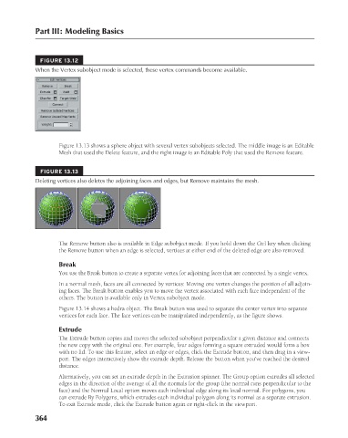
Figure 13.13 shows a sphere object with several vertex subobjects selected. The middle image is an Editable
Mesh that used the Delete feature, and the right image is an Editable Poly that used the Remove feature.
FIGURE 13.13
Deleting vertices also deletes the adjoining faces and edges, but Remove maintains the mesh.
The Remove button also is available in Edge subobject mode. If you hold down the Ctrl key when clicking
the Remove button when an edge is selected, vertices at either end of the deleted edge are also removed.
Break
You use the Break button to create a separate vertex for adjoining faces that are connected by a single vertex.
In a normal mesh, faces are all connected by vertices: Moving one vertex changes the position of all adjoin-
ing faces. The Break button enables you to move the vertex associated with each face independent of the
others. The button is available only in Vertex subobject mode.
Figure 13.14 shows a hedra object. The Break button was used to separate the center vertex into separate
vertices for each face. The face vertices can be manipulated independently, as the figure shows.
Extrude
The Extrude button copies and moves the selected subobject perpendicular a given distance and connects
the new copy with the original one. For example, four edges forming a square extruded would form a box
with no lid. To use this feature, select an edge or edges, click the Extrude button, and then drag in a view-
port. The edges interactively show the extrude depth. Release the button when you’ve reached the desired
distance.
Alternatively, you can set an extrude depth in the Extrusion spinner. The Group option extrudes all selected
edges in the direction of the average of all the normals for the group (the normal runs perpendicular to the
face) and the Normal Local option moves each individual edge along its local normal. For polygons, you
can extrude By Polygons, which extrudes each individual polygon along its normal as a separate extrusion.
To exit Extrude mode, click the Extrude button again or right-click in the viewport.
364
6/30/10 4:23 PM
20_617779-ch13.indd 364
20_617779-ch13.indd 364 6/30/10 4:23 PM