
Page 410 - Kitab3DsMax
P. 410
Part III: Modeling Basics
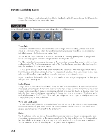
Figure 13.10 shows a simple diamond-shaped hedra that has been MeshSmoothed using the MSmooth but-
ton and then tessellated three consecutive times.
FIGURE 13.10
Using MSmooth reduces the sharp edges, and tessellating adds more editable faces.
Tessellate
Tessellation is used to increase the density of the faces or edges. When modeling, you may want more
details in a select area. This is where the tessellation command comes in. Tessellation can be applied to
individual selected subobjects or to the entire object.
You can use the Tessellate button to increase the resolution of a mesh by splitting a face or polygon into
several faces or polygons. You have two options to do this: Edge and Face.
The Edge method splits each edge at its midpoint. For example, a triangular face would be split into three
smaller triangles. The Tension spinner to the right of the Tessellate button specifies a value that is used to
make the tessellated face concave or convex.
The Face option creates a vertex in the center of the face and also creates three new edges, which extend
from the center vertex to each original vertex. For a square polygon, this option would create six new trian-
gular faces. (Remember, a square polygon is actually composed of two triangular faces.)
Figure 13.11 shows the faces of a cube that has been tessellated once using the Edge option and then again
using the Face-Center option.
Make Planar
A single vertex or two vertices don’t define a plane, but three or more vertices do. If three or more vertices
are selected, you can use the Make Planar button to make these vertices coplanar (which means that all ver-
tices are on the same plane). Doing so positions the selected vertices so that they lie in the same plane. This
is helpful if you want to build a new polygon face. Polygonal faces need to be coplanar. This button works
in all subobject modes. The X, Y, and Z buttons let you collapse the current object or subobject selection to
a single plane lying on the specified axis.
View and Grid Align
The View and Grid Align buttons move and orient all selected vertices to the current active viewport or to
the current construction grid. These buttons can also be used in all subobject modes. This causes all the
selected face normals to point directly at the grid or view.
Relax
The Relax button works just like the Relax modifier by moving vertices so they are as far as possible from
their adjacent vertices according to the Amount value listed in the Settings dialog box. The Settings dialog
box also includes an Iterations value, which determines the number of times the operation is performed.
You can also select to hold all Boundary and Outer points from being moved.
362
6/30/10 4:23 PM
20_617779-ch13.indd 362 6/30/10 4:23 PM
20_617779-ch13.indd 362