
Page 428 - Kitab3DsMax
P. 428
Part III: Modeling Basics
Caution
Even though the patch object looks simple, the resulting surface generates a large number of faces. n
Creating a patch grid
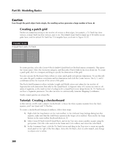
Patches are named according to the number of vertices at their edges; for example, a Tri Patch has three
vertices, a Quad Patch has four vertices, and so on. The default Quad Patch is made up of 36 visible rectan-
gular faces, and the default Tri Patch has 72 triangular faces, as shown in Figure 13.33.
FIGURE 13.33
A Quad Patch and a Tri Patch
To create patches, select the Create ➪ Patch Grids ➪ Quad Patch or Tri Patch menu commands. This opens
the Create panel. Select the Geometry category, and then select Patch Grids in the drop-down list. To create
a patch grid, click in a viewport and drag to specify the dimensions of the grid.
You also can use the Keyboard Entry rollout to create patch grids with precise dimensions. To use this roll-
out, enter the grid’s position coordinates and its dimensions and click the Create button. The X, Y, and Z
coordinates define the location of the center of the grid.
The Patch Grid Parameters rollout includes Length and Width values and values for the number of
Segments for each dimension (but only for the Quad Patch). A Segment value of 1 creates six rows or col-
umns of segments, so the total number of polygons for a Quad Patch never drops below 36. Tri Patches do
not have a Segments parameter. You also can select to automatically Generate Mapping Coordinates.
Newly created patches are always flat.
Tutorial: Creating a checkerboard
In this tutorial, you’ll create a simple checkerboard. To keep the white squares separate from the black
squares, you’ll use Quad and Tri Patches.
To create a checkerboard from patch surfaces, follow these steps:
1. Right-click the Snap button on the main toolbar; in the Grid and Snap Settings dialog box that
appears, make sure that the Grid Points option in the Snaps tab is enabled. Then enable the Snap
button on the main toolbar (keyboard shortcut, S).
2. Select Create ➪ Patch Grids ➪ Quad Patch, and in the Top view create a perfect square using the
grid points. Click the color swatch in the Name and Color rollout, and select the color black.
3. In the Command Panel, click the Tri Patch button and drag in the Top view to create an equally
sized patch to the right of the first object. Select the Tri Patch, click its color swatch, and change
its object color to white.
380
6/30/10 4:23 PM
20_617779-ch13.indd 380
20_617779-ch13.indd 380 6/30/10 4:23 PM