
Page 433 - Kitab3DsMax
P. 433
Chapter 13: Modeling with Polygons and Patches
Surface settings
The View Steps value determines the resolution of the patch grid that is displayed in the viewport. You can
change this resolution for rendering using the Render Steps value. You can turn off the Interior Edges alto-
gether using the Show Interior Edges option. The Use True Patch Normals option sets the type of normal
used to smooth between patch objects. Enabling this option results in more accurate shading.
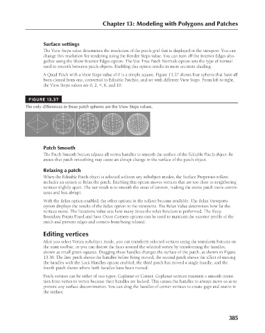
A Quad Patch with a View Steps value of 0 is a simple square. Figure 13.37 shows four spheres that have all
been cloned from one, converted to Editable Patches, and set with different View Steps. From left to right,
the View Steps values are 0, 2, 4, 6, and 10.
FIGURE 13.37
The only differences in these patch spheres are the View Steps values.
Patch Smooth
The Patch Smooth button adjusts all vertex handles to smooth the surface of the Editable Patch object. Be
aware that patch smoothing may cause an abrupt change in the surface of the patch object.
Relaxing a patch
When the Editable Patch object is selected without any subobject modes, the Surface Properties rollout
includes an option to Relax the patch. Enabling this option moves vertices that are too close to neighboring
vertices slightly apart. The net result is to smooth the areas of tension, making the entire patch more contin-
uous and less abrupt.
With the Relax option enabled, the other options in the rollout become available. The Relax Viewports
option displays the results of the Relax option in the viewports. The Relax Value determines how far the
vertices move. The Iterations value sets how many times the relax function is performed. The Keep
Boundary Points Fixed and Save Outer Corners options can be used to maintain the exterior profile of the
patch and prevent edges and corners from being relaxed.
Editing vertices
After you select Vertex subobject mode, you can transform selected vertices using the transform buttons on
the main toolbar, or you can distort the faces around the selected vertex by transforming the handles,
shown as small green squares. Dragging these handles changes the surface of the patch, as shown in Figure
13.38. The first patch shows the handles before being moved, the second patch shows the effect of moving
the handles with the Lock Handles option enabled, the third patch has moved a single handle, and the
fourth patch shows where both handles have been moved.
Patch vertices can be either of two types: Coplanar or Corner. Coplanar vertices maintain a smooth transi-
tion from vertex to vertex because their handles are locked. This causes the handles to always move so as to
prevent any surface discontinuities. You can drag the handles of corner vertices to create gaps and seams in
the surface.
385
6/30/10 4:23 PM
20_617779-ch13.indd 385
20_617779-ch13.indd 385 6/30/10 4:23 PM