
Page 434 - Kitab3DsMax
P. 434
Part III: Modeling Basics
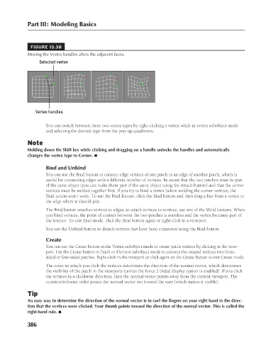
FIGURE 13.38
Moving the Vertex handles alters the adjacent faces.
Selected vertex
Vertex handles
You can switch between these two vertex types by right-clicking a vertex while in vertex subobject mode
and selecting the desired type from the pop-up quadmenu.
Note
Holding down the Shift key while clicking and dragging on a handle unlocks the handles and automatically
changes the vertex type to Corner. n
Bind and Unbind
You can use the Bind button to connect edge vertices of one patch to an edge of another patch, which is
useful for connecting edges with a different number of vertices. Be aware that the two patches must be part
of the same object (you can make them part of the same object using the Attach button) and that the corner
vertices must be welded together first. If you try to bind a vertex before welding the corner vertices, the
Bind action won’t work. To use the Bind feature, click the Bind button and then drag a line from a vertex to
the edge where it should join.
The Bind button attaches vertices to edges; to attach vertices to vertices, use one of the Weld buttons. When
you bind vertices, the point of contact between the two patches is seamless and the vertex becomes part of
the interior. To exit Bind mode, click the Bind button again or right-click in a viewport.
You use the Unbind button to detach vertices that have been connected using the Bind button.
Create
You can use the Create button in the Vertex subobject mode to create patch vertices by clicking in the view-
port. Use the Create button in Patch or Element subobject mode to connect the created vertices into three-
sided or four-sided patches. Right-click in the viewport or click again on the Create button to exit Create mode.
The order in which you click the vertices determines the direction of the normal vector, which determines
the visibility of the patch in the viewports (unless the Force 2-Sided display option is enabled). If you click
the vertices in a clockwise direction, then the normal vector points away from the current viewport. The
counterclockwise order points the normal vector out toward the user (which makes it visible).
Tip
An easy way to determine the direction of the normal vector is to curl the fingers on your right hand in the direc-
tion that the vertices were clicked. Your thumb points toward the direction of the normal vector. This is called the
right-hand rule. n
386
6/30/10 4:23 PM
20_617779-ch13.indd 386 6/30/10 4:23 PM
20_617779-ch13.indd 386