
Page 1342 - Workshop Manual - Aumark (BJ1051)
P. 1342
61-70
Circuit-System circuit diagram
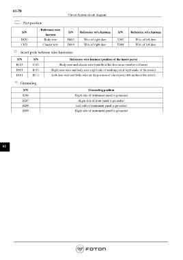
: Part position
Reference wire
S/N S/N Reference wire harness S/N Reference wire harness
harness
B050 Body wire D003 Wire of right door E003 Wire of left door
C051 Chassis wire D004 Wire of right door E004 Wire of left door
: Insert parts between wire harnesses
S/N S/N Reference wire harness (position of the insert parts)
B103 C101 Body wire and chassis wire (middle of the first cross member of frame)
D101 B101 Right door wire and body wire (right side of washing pot at right under of the meter)
E101 B111 Left door wire and body wire (at the position of clutch pedal left under of the meter)
: Grounding
S/N Grounding position
B206 Right side of instrument panel is grounded
B207 Right side of front panel is grounded
B208 Left side of instrument panel is grounded
B209 Right side of instrument panel is grounded
61
Page 1342