
Page 1339 - Workshop Manual - Aumark (BJ1051)
P. 1339
61-67
Circuit-System circuit diagram
Service hint
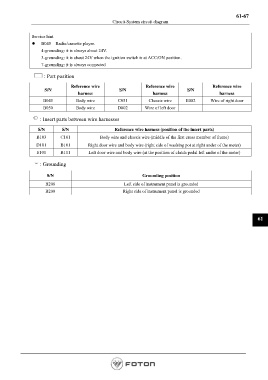
z B045 Radio/cassette player.
4-grounding: it is always about 24V.
3-grounding: it is about 24V when the ignition switch is at ACC/ON position.
7-grounding: it is always connected
: Part position
Reference wire Reference wire Reference wire
S/N S/N S/N
harness harness harness
B045 Body wire C051 Chassis wire E002 Wire of right door
B050 Body wire D002 Wire of left door
: Insert parts between wire harnesses
S/N S/N Reference wire harness (position of the insert parts)
B103 C101 Body wire and chassis wire (middle of the first cross member of frame)
D101 B101 Right door wire and body wire (right side of washing pot at right under of the meter)
E101 B111 Left door wire and body wire (at the position of clutch pedal left under of the meter)
: Grounding
S/N Grounding position
B208 Left side of instrument panel is grounded
B209 Right side of instrument panel is grounded
61
Page 1339